
A Simple Dual H-Bridge

The dual H-bridge circuit configuration allows for bidirectional control of the stepper motor, enabling it to rotate in both clockwise and counterclockwise directions. Each transistor in the H-bridge acts as a switch, controlling the current flow to the motor coils. The transistors 2N3904 (NPN) and 2N3906 (PNP) are used to form the H-bridge, where pairs of transistors are activated in sequence to energize the coils of the stepper motor. This sequential activation creates a rotating magnetic field, which causes the motor to step through its phases.
The Arduino program initializes the control pins as outputs and enters a loop that cycles through a predefined sequence of HIGH and LOW signals. The delays between state changes are crucial for ensuring the stepper motor operates smoothly and accurately. Adjusting the delay values can modify the motor's speed, allowing for fine-tuning based on application requirements.
In practical applications, this setup can be employed in various devices where precise motor control is needed, such as in robotics, automated systems, or any project requiring controlled movement. The simplicity of using discrete transistors combined with the accessibility of Arduino programming makes this dual H-bridge design an excellent choice for hobbyists and engineers alike. The inclusion of an LED indicator in the circuit provides visual feedback of the power status, enhancing usability during development and testing phases.H-bridge is frequently used to control DC motors and stepper motors. When controlling a bipolar stepper motor, two full H-bridges are needed. There are many H-bridge ICs (like L298, MPC17529 and SN754410 which is a quad half H-bridge) for just that purpose. But if you are on a budget, you may want to consider building a dual H-bridge yourself. The following schematic shows a simple dual H-bridge using eight general purpose transistors ( 2N3904 and 2N3906 ). Given the maximum Iceo of roughly 200mA, this circuit can be used to drive a small bipolar stepper motor operating between 5V and 12V, such as the stepper motors found in most floppy drives and CD/DVD drives. The four control inputs (1, 2, 3, 4) can be driven with Arduino s digital pins (i. e. 2, 3, 4, 5) directly. The following program illustrates how to signal the four leads of a bipolar stepper motor for it to rotate.
Of course, there`s already a stepper motor library built for this purpose. The program below is helpful when learning the sequence of the pulses required by bipolar stepper motors. int coila1 = 2; int coila2 = 3; int coilb1 = 4; int coilb2 = 5; void setup() { pinMode(coila1, OUTPUT); pinMode(coila2, OUTPUT); pinMode(coilb1, OUTPUT); pinMode(coilb2, OUTPUT); } void loop() { digitalWrite(coila1, HIGH); digitalWrite(coila2, LOW); digitalWrite(coilb1, LOW); digitalWrite(coilb2, LOW); delay(10); digitalWrite(coila1, LOW); digitalWrite(coila2, LOW); digitalWrite(coilb1, HIGH); digitalWrite(coilb2, LOW); delay(01); digitalWrite(coila1, LOW); digitalWrite(coila2, HIGH); digitalWrite(coilb1, LOW); digitalWrite(coilb2, LOW); delay(10); digitalWrite(coila1, LOW); digitalWrite(coila2, LOW); digitalWrite(coilb1, LOW); digitalWrite(coilb2, HIGH); delay(10); } Here is a picture of an Arduino controlled CD-ROM stepper motor (the one controlling the tray mechanism) powered by the above dual H-bridge (with an added LED for power).
🔗 External reference
Related Circuits
In appliances that require alternating current, NiCad (NiCd) rechargeable batteries still demonstrate significant performance advantages compared to NiMH and lithium batteries. The charger circuit is critical in handling incorrect polarity of the battery placement. The core of this battery...
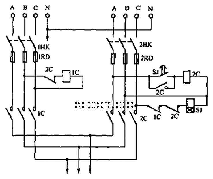
A dual three-phase power line circuit is illustrated in the figure. When the knife switches 1HK and 2HK are closed simultaneously, the normally closed contact 1C disconnects the power supply to the time relay SJ, allowing power to reach...
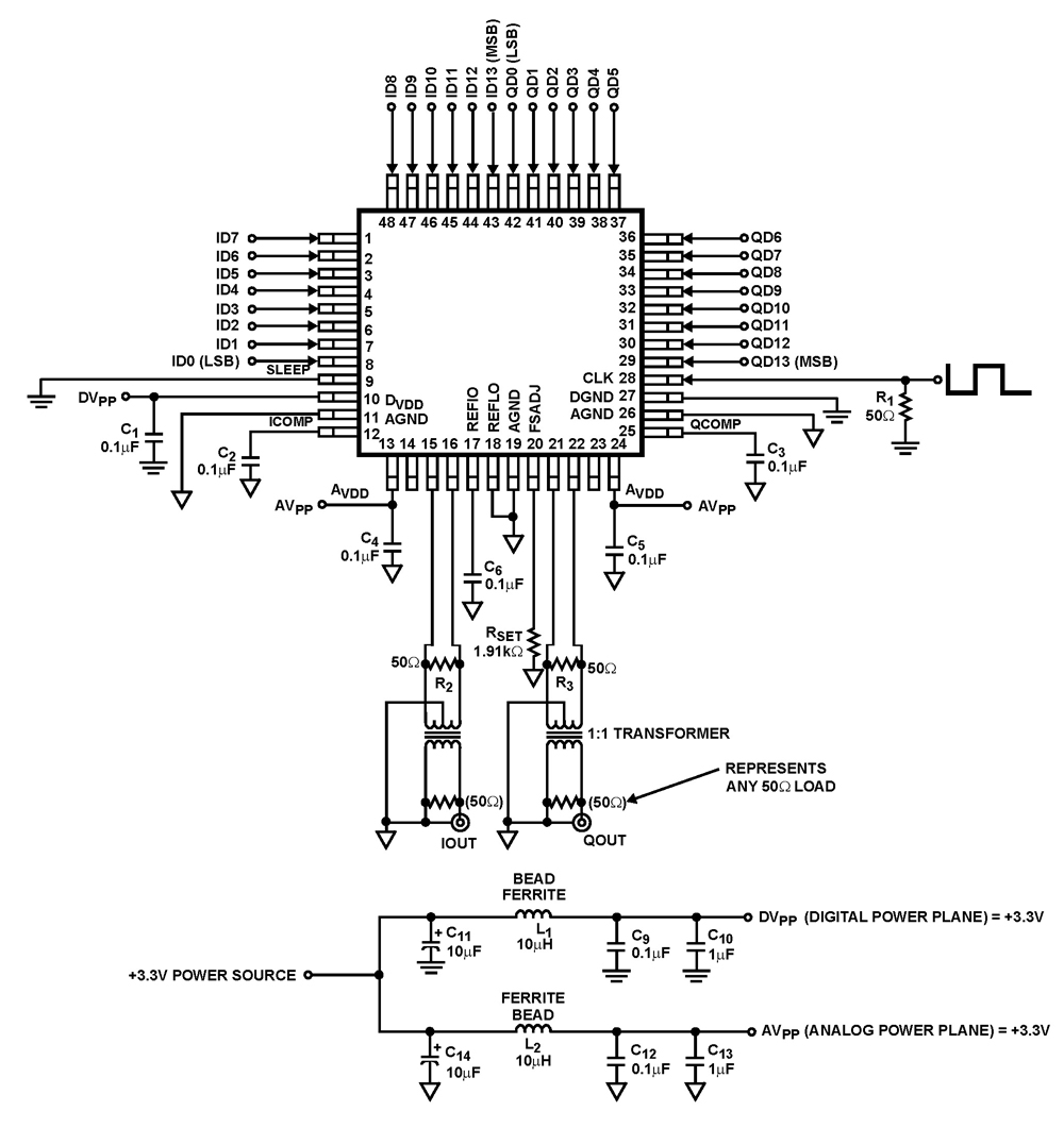
The ISL5929 is a dual 14-bit, 130/210+ MSPS (Mega Samples Per Second), CMOS, high-speed, low-power, digital-to-analog converter (DAC) designed specifically for high-performance communication systems, such as base transceiver stations utilizing 2.5G or 3G cellular protocols. The ISL5929 DAC is engineered...
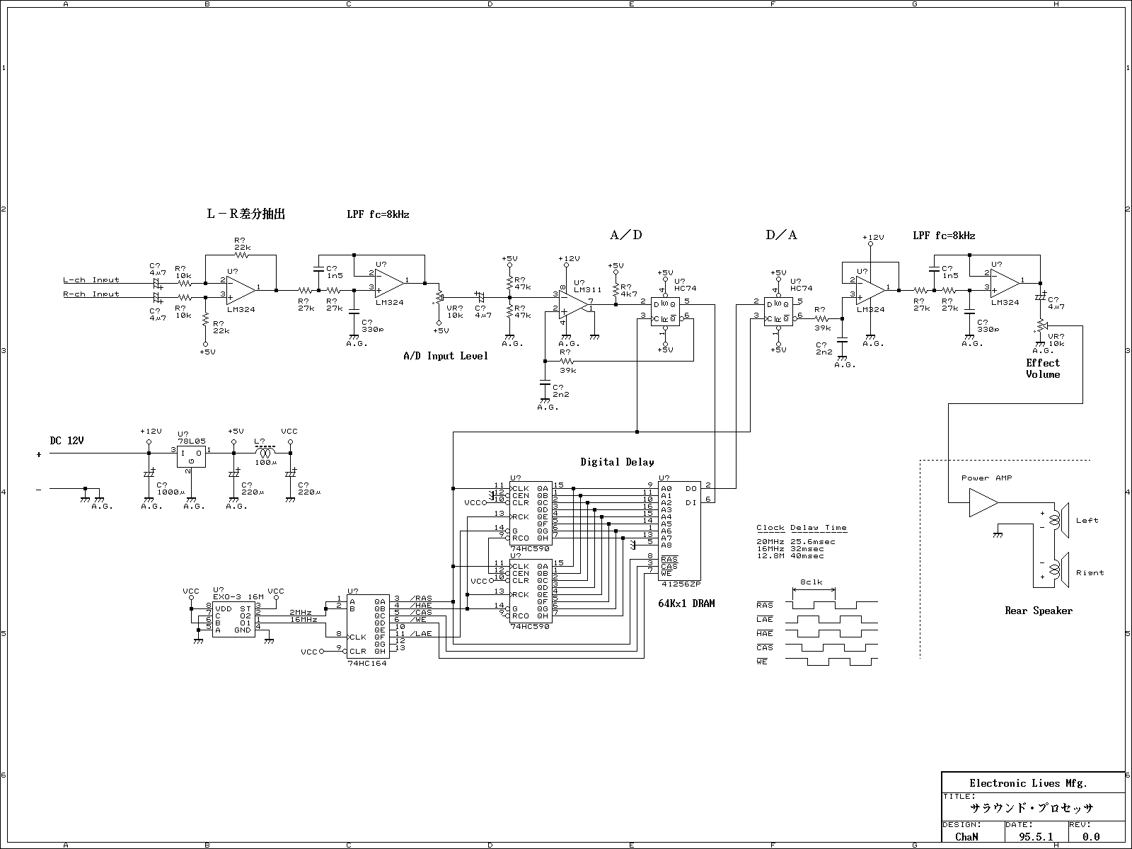
This is a simple Surround Processor with the digital delay method. This audio processor is not using any special function ICs that are difficult to obtain personally and is designed using only general-purpose ICs. The Digital Delay Block of...
In this circuit, the 7815 regulates the positive supply, and the 7915 regulates the negative supply. The transformer should have a primary rating of 240/220 volts for Europe, or 120 volts for North America. The centre-tapped secondary coil should...
A versatile circuit of an IF signal generator that may be of interest to radio hobbyists and professionals alike. Transistors T1 and T2 form an astable multivibrator oscillating in the audio frequency range of 1 to 2 kHz. An...