
A Simple Programmer for PIC18F14K50 Microcontroller
The Microchip PIC18F14K50 microcontroller is a member of the PIC18 family, known for its high performance and versatility. It features a 28-pin package, making it suitable for space-constrained applications. The device operates at a maximum clock speed of 48 MHz and is equipped with 32 KB of flash memory, 2 KB of RAM, and 256 bytes of EEPROM, providing ample resources for a variety of embedded applications.
One of the key aspects of the PIC18F14K50 is its USB interface, which supports full-speed USB 2.0 connectivity. This feature is particularly beneficial for applications requiring direct communication with host devices such as computers or USB hubs. The microcontroller also includes multiple I/O ports, allowing for the connection of various peripherals, sensors, and actuators, enhancing its functionality in different projects.
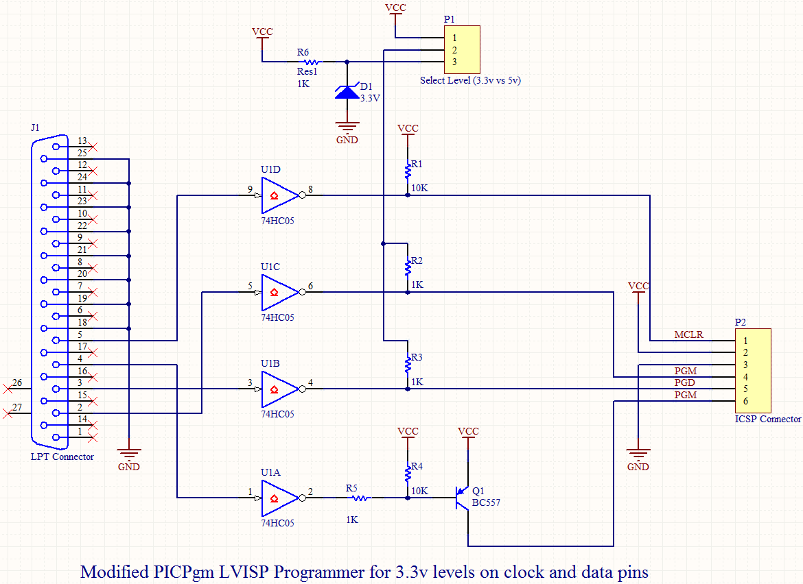
It is crucial to note that the flash programming of the PIC18F14K50 requires the manipulation of two specific pins, typically referred to as MCLR (Master Clear) and PGD/PGC (Programming Data/Clock). These pins must be correctly driven during the programming process to ensure successful flash memory updates. Failure to adhere to this requirement can result in programming errors or device malfunctions.
Designers utilizing the PIC18F14K50 should incorporate these considerations into their schematics to facilitate proper programming and functionality. The integration of decoupling capacitors near the power supply pins is recommended to enhance stability and reduce noise. Additionally, pull-up resistors may be necessary on the MCLR pin to ensure reliable operation during reset conditions.
In conclusion, the PIC18F14K50 microcontroller is a powerful and cost-effective solution for a wide range of applications, particularly those requiring USB connectivity. Attention to its unique programming requirements and careful schematic design will ensure optimal performance and reliability in the final product.Microchip`s PIC18F14K50 is fantastic: almost anything you need in a small footprint for a low price! Absorbed in many good features of this chip, I neglected a special requirement for its flash programming when I was designing a small USB board. Unlike many other PICs, you have to drive two programming pins of this micro.. 🔗 External reference
Related Circuits
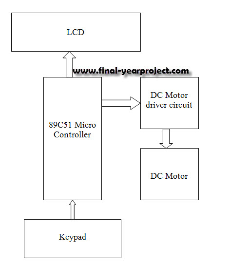
This report details an electronic project focused on the speed control of a DC motor using a microcontroller and PWM (Pulse Width Modulation). The system integrates a microcontroller with an LCD, keypad, and a DC motor driver. The microcontroller...
This is a straightforward circuit designed for charging lead-acid batteries using the PB137 regulator. The PB137 is utilized in the lead-acid battery charger circuit due to its ability to provide... The PB137 voltage regulator is a linear regulator specifically suited...
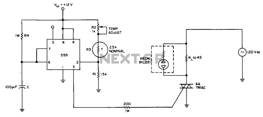
The internal comparator of the 555 timer, combined with a thermistor, creates a low-cost temperature controller. Resistor R2 establishes the temperature trip point. The 555 timer is a versatile integrated circuit widely used in various applications, including timers, oscillators, and...
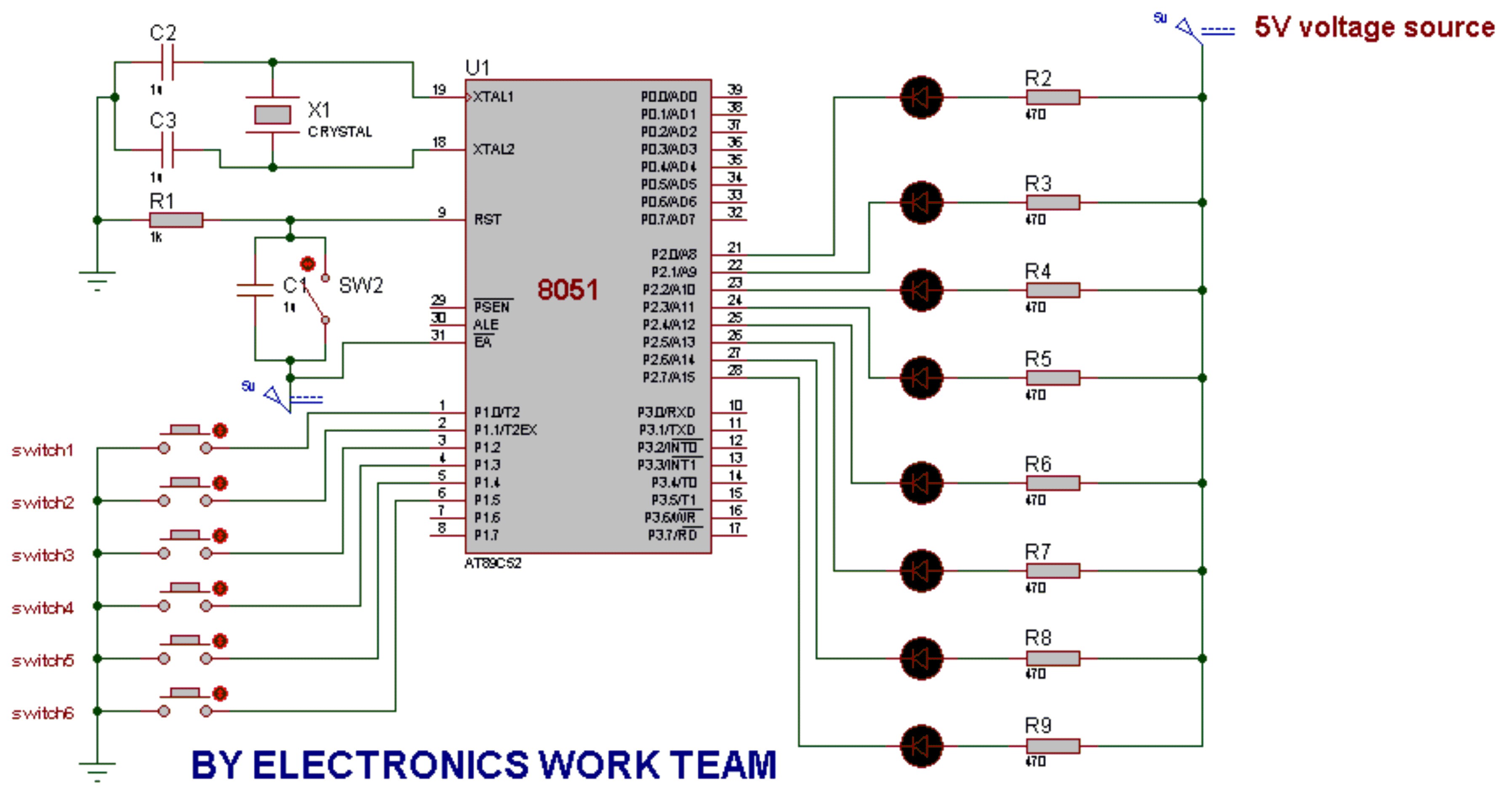
This post discusses the fundamental operation of the 8051 microcontroller using LEDs. The LEDs are connected to the P2 port, while six switches are connected to the P1 port of the 8051. By pressing various switches, the LEDs will...
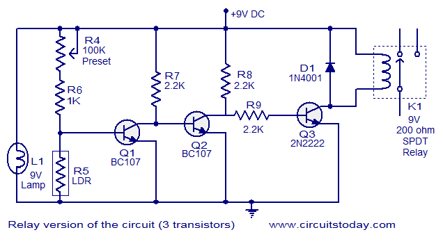
This document describes a simple fire alarm circuit utilizing a Light Dependent Resistor (LDR) and lamp combination for fire detection. The alarm activates by detecting smoke generated during a fire. When smoke is present, the circuit triggers an audible...

Utilize the Maxim MAX292 switched-capacitor filter integrated circuit to convert a square wave into a sine wave. The operational frequency range of the circuit spans from 5.2282 Hz to 8928.6 Hz when the microcontroller is functioning at a 16-MHz...
Warning: include(partials/cookie-banner.php): Failed to open stream: Permission denied in /var/www/html/nextgr/view-circuit.php on line 713
Warning: include(): Failed opening 'partials/cookie-banner.php' for inclusion (include_path='.:/usr/share/php') in /var/www/html/nextgr/view-circuit.php on line 713