
Speed Control of DC Motor using Microcontroller by using PWM ECE Project
The project utilizes the AT89C51 microcontroller, which is a widely used 8-bit microcontroller based on the MCS-51 architecture. It features a 4KB ROM, 128 bytes of RAM, and multiple I/O ports, making it suitable for various control applications. In this speed control application, the microcontroller's PWM capabilities allow for precise control over the motor's speed by adjusting the duty cycle of the PWM signal.
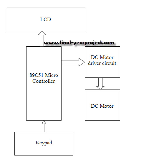
The system design includes several key components:
1. **Microcontroller (AT89C51)**: Acts as the central processing unit, generating PWM signals based on user input.
2. **LCD Display**: Provides a user interface for displaying the current speed of the DC motor and other relevant information. It is interfaced with the microcontroller to present real-time data.
3. **Keypad**: Serves as the input device for the user to set the desired speed of the DC motor. The keypad inputs are processed by the microcontroller to adjust the PWM signal accordingly.
4. **DC Motor Driver**: This component amplifies the PWM signal from the microcontroller to drive the DC motor. It ensures that the motor receives the necessary current and voltage for operation.
5. **DC Motor**: The actuator that converts electrical energy into mechanical energy, allowing for variable speed operation based on PWM input.
The PWM technique is employed to control the average voltage supplied to the motor, effectively regulating its speed. By varying the duty cycle of the PWM signal, the average power delivered to the motor can be controlled, resulting in precise speed adjustments. The block diagram of the system visually represents the interconnections among these components, highlighting the flow of signals and power.
In conclusion, this project serves as an excellent reference for understanding the implementation of speed control in DC motors using microcontrollers and PWM. It provides insights into hardware interfacing, programming, and the principles of motor control, making it a valuable resource for electronics students and professionals.This is a good Electronic project report on Speed Control of DC Motor using Microcontroller by using PWM. In this system, a micro controller is interfaced with a LCD, Keypad and DC motor driver. The Micro controller is used for controlling the DC motor by producing the PWM pulses. These pulse widths are produced according to the key pad register v alues which are allotted by MC. You can also Subscribe to FINAL YEAR PROJECT`S by Email for more such projects and seminar. In this project AT89C51 microcontroller is used as speed controller. In the above block diagram we are using one keypad, LCD, one driver circuit for DC motor and DC Motor. The report contains description of microcontroller and project with complete ALP programming. Use it for your reference and study work only. 🔗 External reference
Related Circuits
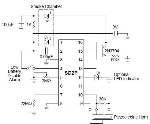
This smoke detector circuit diagram is based on the SD2 CMOS Photo-Electric Smoke Detector Integrated Circuit manufactured by Supertex Inc. It includes almost all the necessary components to build a simple and highly efficient smoke detector project. The LED...
The prototype was successfully assembled on a breadboard and subsequently built on a piece of Radio Shack protoboard for field use. The assembly process took only a couple of hours, and it functioned correctly on the first attempt. This...

This circuit utilizes a 4049 integrated circuit (IC) to control a 2N2222 switching transistor. The transistor, in turn, drives a piezo transducer known as crystal 1. The circuit design begins with the 4049 IC, which is a hex inverter capable...
The circuit does not require a separate power switch or transformation to control the switches on the table. It offers advantages such as low power consumption, stability, reliability, and no impact on instrument accuracy. The transformer T in the...
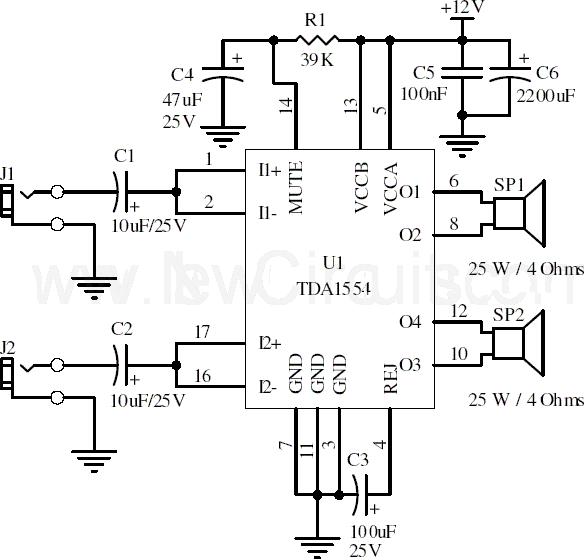
This document presents a 22-watt stereo audio power amplifier circuit diagram utilizing the TDA1554 integrated circuit from NXP Semiconductors (formerly known as PHILIPS Semiconductors). The circuit is designed to amplify stereo signals effectively. It dissipates approximately 28 watts of...
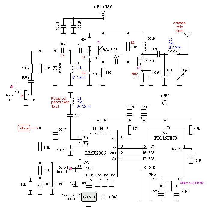
This oscillator is known as the Colpitts oscillator and is voltage-controlled to facilitate frequency modulation (FM) and phase-locked loop (PLL) control. The transistor T1 should be a high-frequency (HF) transistor for optimal performance; however, in this instance, a common...