
Very Simple Lead Acid Battery Charger with PB137 Regulator

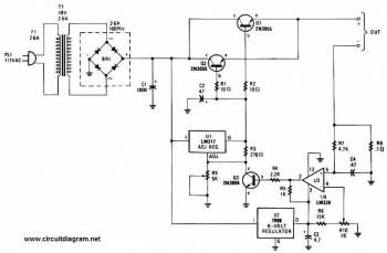
The PB137 voltage regulator is a linear regulator specifically suited for applications requiring stable output voltage and current regulation, making it an ideal choice for charging lead-acid batteries. This circuit typically operates with an input voltage that exceeds the desired output voltage, allowing the PB137 to regulate the voltage down to a safe level for charging.
The circuit configuration usually consists of the PB137 connected to a transformer that steps down the mains voltage to a lower AC voltage. This AC voltage is then rectified using a bridge rectifier to convert it into DC voltage. A smoothing capacitor is often included after the rectifier to reduce ripple voltage and provide a more stable DC output.
To ensure proper charging of the lead-acid battery, a current-limiting resistor may be implemented in series with the output. This resistor helps to prevent excessive current from flowing into the battery, which could lead to damage or reduced lifespan. Additionally, a diode may be placed in parallel with the battery to prevent reverse current flow when the charger is not in operation.
The output voltage of the PB137 is typically set to around 13.8 to 14.4 volts, which is suitable for charging most lead-acid batteries. It is essential to monitor the charging process, as overcharging can result in gassing and battery damage. Therefore, a simple LED indicator can be included to signal when the battery is charging and when it is fully charged.
Overall, this circuit provides a reliable and efficient means of charging lead-acid batteries, leveraging the capabilities of the PB137 voltage regulator to ensure safe and effective operation.This is a Very Simple circuit for Lead Acid Battery Charger using PB137 Regulator. The PB137 is used for lead acid battery charger circuit because it can give.. 🔗 External reference
Related Circuits
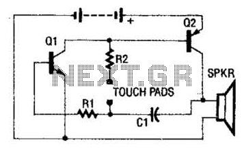
The circuit employs a two-transistor direct-coupled oscillator, with its frequency determined by capacitor C1, resistor R2, and the skin resistance across the touch pads. Since C1 and R2 are fixed values, only the skin resistance can vary the sound...
This battery charger circuit is regulated and adjustable, enabling it to charge most NiCAD batteries. It can accommodate both single cells and multiple battery cells connected in series or parallel. The maximum voltage of the batteries should not exceed...
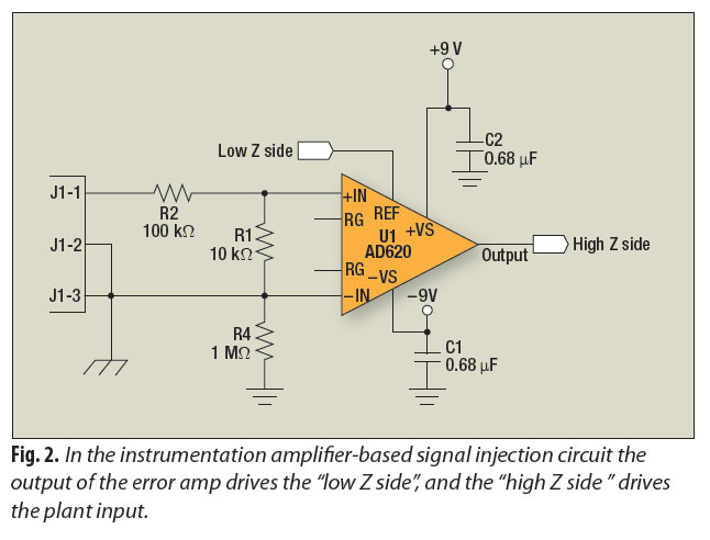
A signal-injection circuit for control-loop analysis is flat from DC to 200 kHz, isolated from chassis ground, and easily constructed with a readily available instrumentation amplifier. The signal-injection circuit is designed to facilitate control-loop analysis by providing a stable and...
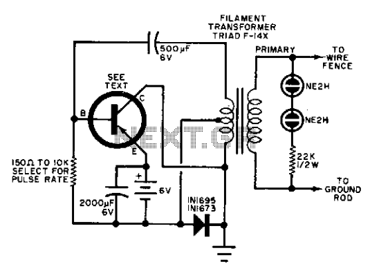
Any suitable power transistor can be utilized in this circuit. The base resistor must be calibrated to achieve a pulse rate of approximately 50 pulses per minute, with a possible range from 10 to 100 pulses per minute. The...
A simple oscillator that can be utilized for code practice. To achieve adequate inductance for generating an audio frequency, an iron core transformer, similar to those employed in audio transformer-coupled amplifiers, is connected as illustrated. The circuit comprises a basic...
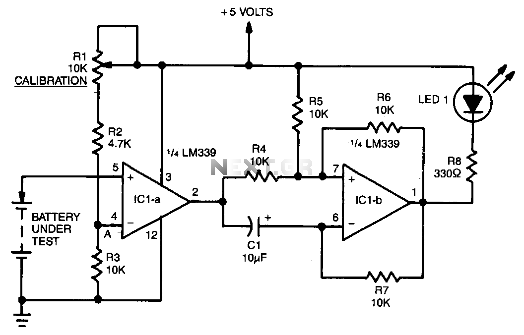
A voltage divider consisting of R1, R2, and R3 is utilized to establish the input reference voltage below which the batteries should be replaced. The reference voltage at point A is adjustable via R1. As illustrated in the diagram,...