
A Simple Radio Receiver
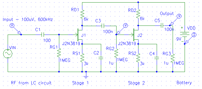
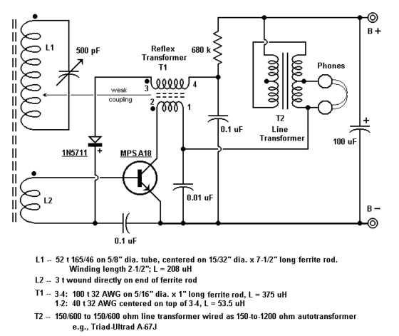
The modular radio receiver design employs several critical components to achieve its functionality. The LC circuit, consisting of the inductor L1 and variable capacitor VC1, serves as the heart of the tuning mechanism. The inductance of 729 µH combined with the variable capacitance allows for fine-tuning within the Medium Wave band, enabling the user to select different radio stations. The choice of ferrite material for L1 is particularly advantageous, as it enhances the inductive properties while minimizing the physical size of the coil, thus improving overall efficiency.
The auxiliary coil L2 functions as a coupling mechanism, facilitating the transfer of energy from the antenna to the LC circuit without requiring direct connection, which could lead to signal loss or interference. This transformer-like behavior is essential for amplifying weak signals captured from the airwaves, making it possible to listen to distant broadcasts.
The use of a diode detector is critical in the demodulation process, as it allows for the extraction of the audio signal from the amplitude-modulated carrier wave. The configuration of capacitor C7 plays a vital role in this process, ensuring that the audio frequencies are effectively coupled to the output stage of the receiver.
Overall, the design of this modular radio receiver exemplifies fundamental principles of electronics, showcasing the integration of passive components to create a functional device capable of receiving and demodulating radio signals. This project not only serves as an educational tool but also highlights the historical significance of crystal sets in the evolution of radio technology.The diagrams below detail the development of a simple modular radio receiver based entirely on circuits and devices studied during the Part IA course on Linear Circuits and Devices. This receiver may not take the market by storm! However, we hope it will help illustrate how the circuits and principles we are studying all c ontribute to the art of electronic circuit design. A crystal set does not have a battery. It runs completely from the energy extracted from radio waves it picks up from the antenna. A resonant LC (or tuned) circuit coupled to a large aerial or antenna was used. Many amateur experimenters constructed crystal sets, often with the tuner inductor coil wound on a tubular box or a drinking glass. At this time the semiconductor diode had not been invented, so extracting the audible modulation signal from the transmission relied on the non-linear electrical properties of the `crystal`, typically a piece of coke or galena.
In early sets a "cat`s whiskers" - a fine piece of wire - was adjusted by trial and error to make a suitable contact with the crystal. There were many limitations to the crystal set: it needed a big aerial (antenna), an earth connection, the clumsy cat`s whisker, and the weak signal could only be listened to by one person at a time with headphones.
Very quickly the crystal set began to be replaced by valve radios with loudspeakers, powered by batteries. In World War II, crystal sets were used by prisoners of war in prison camps to listen to news from home.
Much ingenuity went into improvising the necessary components. The design shown here is a little more complex than strictly necessary, but some of the adaptations incorporated make it easier to develop the design, adding amplifiers and other stages as we meet them in the course. Circuit (a) alongside shows the LC resonant circuit comprising L1 and VC1 used to select or tune the required frequency and station.
The inductance used is 729 uH, and VC1 can be varied over a range 30 to 234 pF. That means the range of resonant frequencies is about 400 to 1075 kHz, which includes a good part of the Medium Wave band of frequencies. L1 is a coil of wire wound on a ferrite rod. Ferrite is a material with a high magnetic permeability - that simply means that that to achieve a given inductance, a smaller number of turns is required than if the coil had an air core.
That keeps its winding resistance low, and enhances the Q, which in turn means the resonant circuit has a narrower resonance peak, and is better at rejecting unwanted frequencies. VC1 is a variable capacitor, in which the capacitance is varied by rotating a knob, which controls the extent to which a set of small parallel plates are enmeshed.
The capacitance can never be reduced to zero, of course, owing to the residual capacitances due to its structure. To these figures must be added any stray or parasitic capacitances arising from the connecting wires, circuit board, and other elements.
These can never be eliminated, but careful construction aims to keep them down to a few tens of pF. The signal from the antenna (perhaps a few tens of microvolts, or hundreds for a nearby transmitting station) is introduced to the LC circuit either through a small capacitance, or, as in this case, by means of a second coil L2 wound on top of L1, with its other end connected to earth. This behaves like a transformer - currents flowing in L2 generate a changing magnetic flux which cuts L1 and induces an emf in it.
Transmissions on Medium Wave frequencies are by Amplitude Modulation. The amplitude of the transmitted radio signal or carrier is modulated - made to rise and fall - by another signal of audible frequency - for example, speech or music. The receiver must extract or detect this audio signal by separating it from the carrier. One way of doinjg this is by means of a diode detector. The signal is introduced via capacitor C7 🔗 External reference
Related Circuits
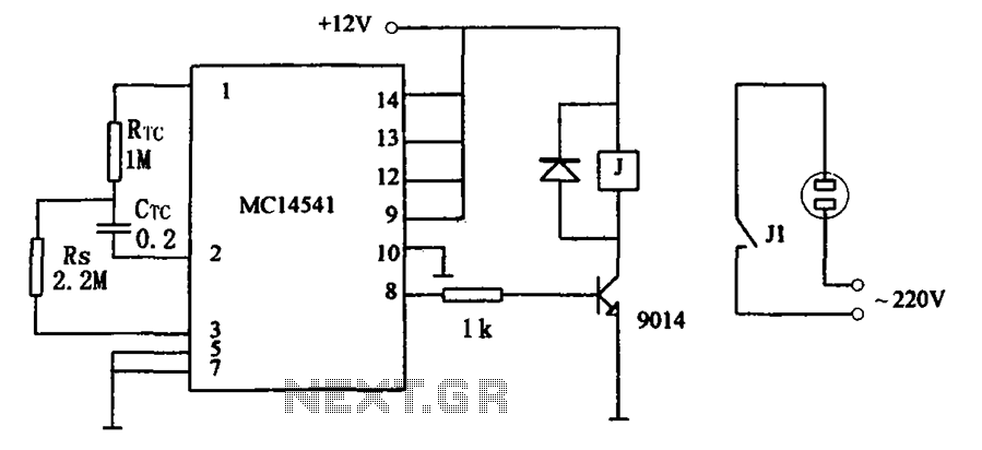
The circuit illustrated in FIG MC14541 is a straightforward timing circuit utilizing the MC14541 integrated circuit (IC). By adjusting the parameter map, the timing can be set for a duration of 3 hours, with options to select various RTC,...
This circuit diagram represents a simple yet effective transmitter circuit, capable of transmitting telephone conversations. When the telephone receiver is on the hook, the line voltage is approximately 48 volts. The R7 preset resistor is adjusted to achieve a...
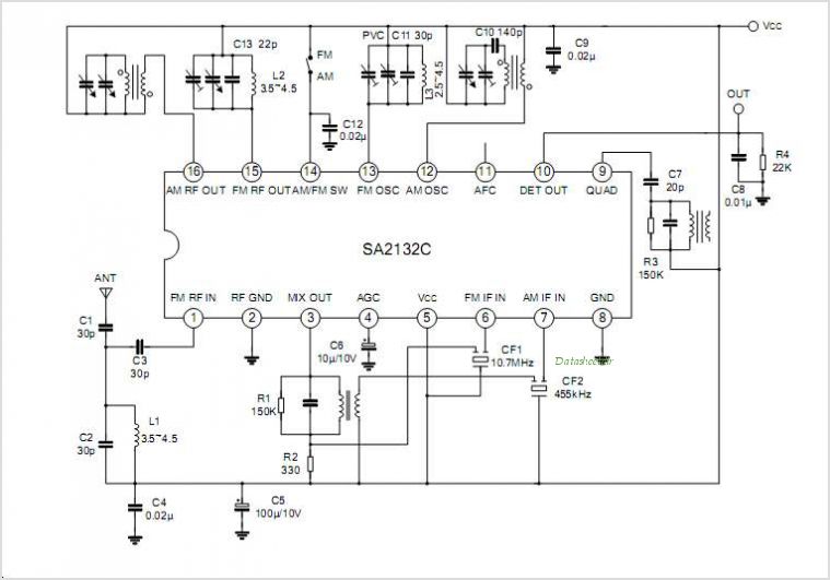
The SA605 is a high-performance monolithic low-power FM intermediate frequency (IF) system that integrates a mixer, oscillator, two limiting intermediate frequency amplifiers, a quadrature detector, muting, a logarithmic received signal strength indicator (RSSI), and a voltage regulator. It combines...
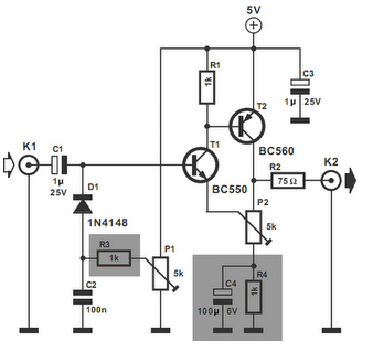
The video amplifier in the diagram represents a well-established design that is both simple and highly functional. However, it is important to note that the transistors can be easily damaged if the potentiometers (black level and signal amplitude) are...
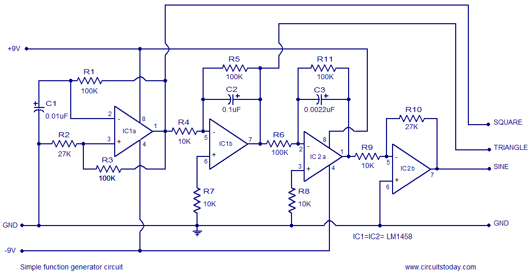
A simple function generator circuit utilizing the LM1458 is presented here. The LM1458 is a dual general-purpose operational amplifier. The two op-amps within the LM1458 share a common bias network and power supply line, yet operate independently. The function generator...
The Birmingham, Alabama Crystal Radio Group website serves as the host for the crystal radio receiving contest. This page provides information about the group and its activities related to crystal sets, including details about the 2008 contest radios. The Birmingham,...
Warning: include(partials/cookie-banner.php): Failed to open stream: Permission denied in /var/www/html/nextgr/view-circuit.php on line 713
Warning: include(): Failed opening 'partials/cookie-banner.php' for inclusion (include_path='.:/usr/share/php') in /var/www/html/nextgr/view-circuit.php on line 713