
simple 15v powered led flasher circuit

The circuit operates at a nominal input voltage of 1.5V, which is suitable for battery-powered applications. The core component, the BC557 transistor, is used in a switching configuration. When the circuit is powered, the transistor is activated, allowing current to flow through the 100µF capacitor. The capacitor stores energy and, once charged to a sufficient voltage level, discharges through the LED, causing it to illuminate.
The choice of LED voltage ratings (1.7V or 2.3V) is significant, as it determines the brightness and color of the emitted light. Different colors of LEDs have varying forward voltage requirements; hence, the circuit's ability to flash these LEDs demonstrates its versatility. The charge-pump mechanism is particularly effective in this design, as it allows the circuit to boost the voltage from the 1.5V supply to a level sufficient to drive the LED.
In terms of component selection, the electrolytic capacitor must be rated for a voltage higher than the expected peak voltage during discharge to ensure reliability and safety. Additionally, the use of a resistor in series with the LED may be necessary to limit the current and protect the LED from excessive current, which could lead to failure.
The overall simplicity of the circuit makes it an excellent choice for educational purposes, as well as for hobbyist projects. It effectively demonstrates principles of charge storage, voltage boosting, and basic transistor switching, providing a practical application for these fundamental concepts in electronics.This is a simple 1. 5V powered LED Flasher circuit diagram. This circuit can flash 1. 7V or 2. 3V LED (depend on the color) using 1. 5Vdc input. The LED will turn on when the 100u capacitor jacked up by the collector of BC557. The circuit is a charge-pump design. This is where a capacitor (electrolytic) is allowed to charge and is then raised highe r and allowed to discharge into a load. The load sees a voltage that can be higher than the supply. 🔗 External reference
Related Circuits
The circuit described is a simple intercom system that utilizes a single LM386 integrated circuit, a 2N3904 transistor, and several additional components. The LM386 is a widely recognized amplifier IC commonly employed by electronics enthusiasts in audio applications. In...
Flashing frequency can be varied by changing R1 value in the 1M - 4M7 range. This circuit is very efficient when driving a small 3.2V incandescent lamp. In this case omit the LED and R3, connecting the bulb across...

Using TRW part number CA-815H, a 17 dB gain amplifier capable of delivering 100 mW over a frequency range of 10 to 1000 MHz can be constructed. Additionally, the CA-2870 can provide 0.4 W with a gain of 34...
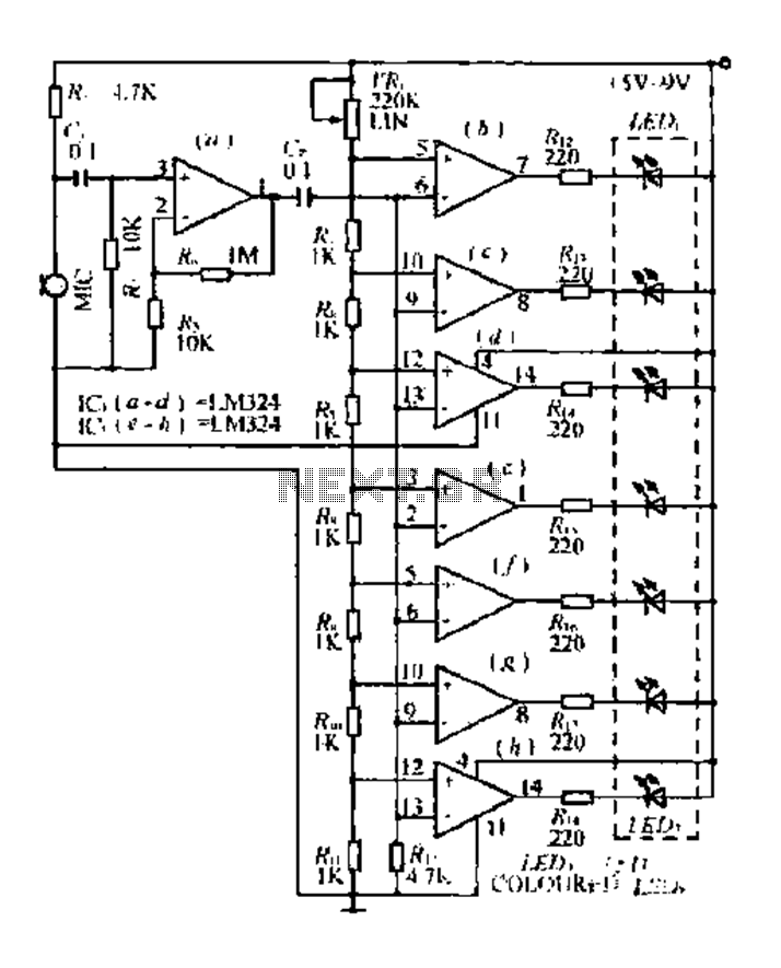
The condenser microphone pickup signal is processed by an integrated circuit (IC) where it is amplified and compared using a comparator circuit. The outputs from the comparators, designated as IC1, IC2, and IC3, provide voltage comparisons based on different...

This halogen switch circuit utilizes a FET transistor, as the current is influenced by the gate voltage of the FET. The maximum gate voltage is 12V, making the circuit suitable for 12-volt lamps. The resistor R1 has a value...
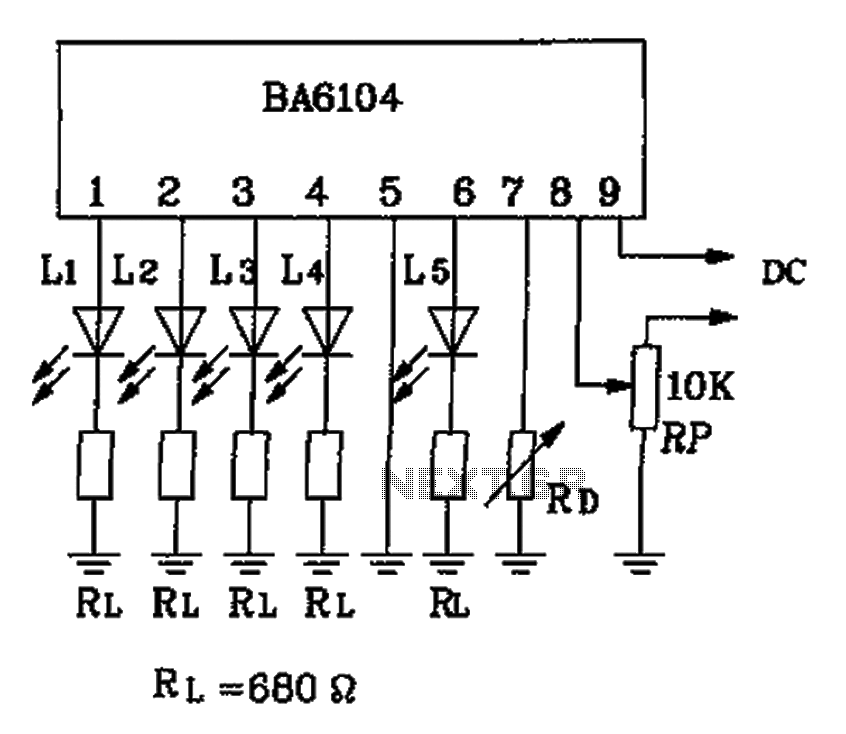
The BA6104 is a five-digit LED level meter driver integrated circuit (IC) used in basic application circuits. When the input level exceeds the required display threshold of 1V, only 7 feet of the power supply Vcc are indirectly affected...