
Battery charger circuit using L200
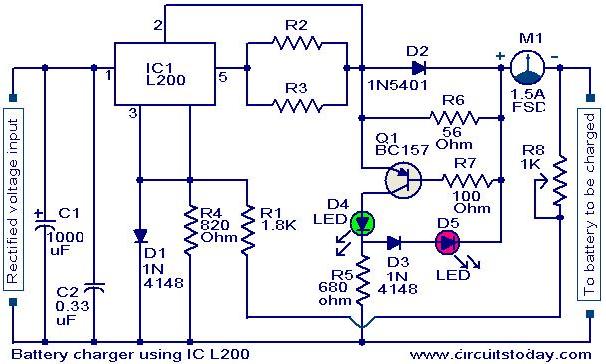
The battery charger circuit described employs the L200 voltage regulator, which is notable for its ability to provide a stable output voltage, essential for safely charging lead-acid batteries. The circuit configuration allows it to be powered from a DC source, typically provided by a rectifier setup that converts AC to DC voltage.
To optimize the charging process, the resistors R2 and R3 are chosen to set the desired charging current, which is critical for the longevity and health of the battery being charged. The use of a potentiometer (P1) allows for fine-tuning of this current, accommodating variations in battery condition and ensuring that the charging process is efficient and safe.
The inclusion of a reverse polarity protection mechanism is a significant safety feature. The circuit utilizes a transistor (T1) and a diode (D3) in conjunction with two LEDs (D4 and D5) to provide visual indicators of the charging status. The green LED (D4) illuminates when the battery is charging correctly, while the red LED (D5) serves as an alert if the battery is connected in the wrong orientation. This feature prevents potential damage to the battery and the circuit itself due to incorrect connections.
Overall, this battery charger circuit is designed with user safety and operational reliability in mind, making it suitable for charging 12 V lead-acid batteries in various applications. Proper selection of components and careful attention to circuit design principles ensure that the charger operates effectively within its intended parameters.A very simple battery charger circuit having reverse polarity indication is shown here. The circuit is based on IC L200. L200 is a five pin variable voltage voltage regulator IC. The charging circuit can be fed by the DC voltage from a bridge rectifier or center tapped rectifier. Here the IC L200 keeps the charging voltage constant. The charging curr ent is controlled by the parallel combination of the resistors R2 & R3. The POT P1 can be used to adjust the charging current. This circuit is designed to charge a 12 V lead acid battery. The transistor t1, diode D3 and LED are used to make a battery reverse indicator. In case the battery is connected in reverse polarity, the reverse polarity indicator red LED D5 glows. When the charging process is going on the battery charging indicator green LED D4 glows. 🔗 External reference
Related Circuits
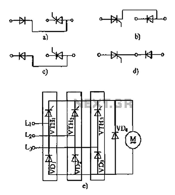
The thyristor linking arm rectifier module is a three-phase half-controlled bridge rectifier circuit. The thyristor-rectifier module linking arm consists of a thyristor and a rectifier diode connected in series or parallel, designed to fulfill specific requirements in power circuits....
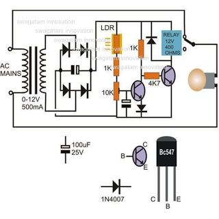
This circuit diagram illustrates a light-activated switch utilizing the National Semiconductor comparator IC LM311 and a light-dependent resistor (LDR). The configuration is based on a voltage comparator circuit centered around IC1. The non-inverting input of IC1 receives a reference...
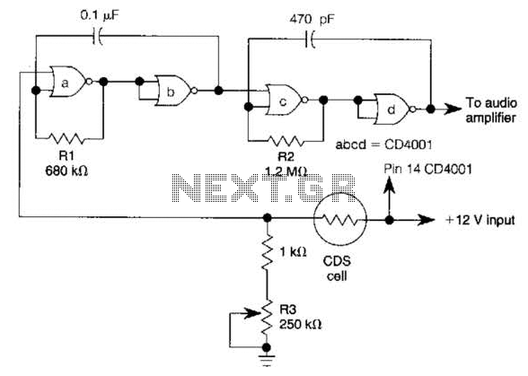
NOR gates A and B create a low-frequency oscillator that activates when the CDS cell, in dark conditions, presents a logic zero to one input of NOR gate A. This low-frequency oscillator, operating at 10 Hz, enables a high-frequency...
The 555 circuit can be re-triggered if the input is held low for a duration longer than the output pulse. To prevent this from occurring, an additional timing circuit has been incorporated, consisting of a 1 Megohm resistor and...
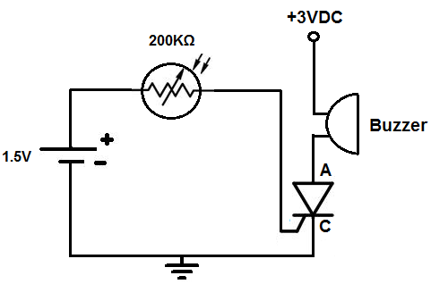
This circuit activates an alarm when it detects a specific level of light. When the light exposure increases beyond a predetermined threshold, a loud buzzer sounds, providing an alert. The alarm remains inactive in low-light conditions but triggers in...
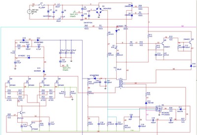
A Power Factor Correction (PFC) board has been obtained from an old Sun Microsystems Spark450 power supply (part number 300-1359-xx). This board contains all necessary components for a 650-watt inverter. However, the complete PFC circuit is not fully detailed...