
Make Your Own USB Device using PIC18F4550
This project involves designing a USB generic Human Interface Device (HID) utilizing a breadboard setup, centered around the PIC18F4550 microcontroller. The tutorial begins by explaining the necessary components and their functions, followed by step-by-step instructions for assembling the circuit. The PIC18F4550 is chosen for its built-in USB capabilities, which facilitate direct communication with a host computer without the need for additional hardware.
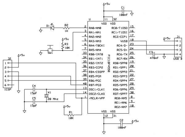
The power for the device is supplied directly from the USB host, simplifying the circuit design as no external power regulation is required. The inclusion of a 470nF capacitor (C3) is crucial, as it stabilizes the voltage levels necessary for the microcontroller's internal USB circuitry, ensuring reliable operation during data transmission.
An In-Circuit Serial Programming (ICSP) header is integrated into the design, allowing for easy programming of the PIC18F4550. The PICkit2 programmer is recommended for its affordability and compatibility, although other ICSP-compatible programmers can also be utilized. This feature enables rapid development and debugging of the firmware.
For the firmware development, the MPLAB Integrated Development Environment (IDE) and the Hi-Tech C compiler are employed, both of which are freely available. This software will facilitate the creation of the necessary code to manage the USB communications, LED control, and button state reading.
On the software side, a Windows interface is developed using Microsoft Visual C++ 2008 Express, which allows users to interact with the device easily. This interface will provide controls for the LED and display the status of the push-button, reinforcing the principles of two-way USB communication.
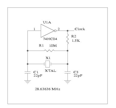
The microcontroller operates at a base clock frequency of 20MHz, which is essential for USB applications. This clock speed is increased to 48MHz using Phase-Locked Loop (PLL) techniques within the microcontroller, enabling it to meet the USB communication requirements.
Overall, this project serves as an excellent introduction to USB device development, illustrating essential concepts in microcontroller programming, circuit design, and software interface creation. The knowledge gained from this experience can be applied to more advanced USB projects in the future.If you are looking to learn how to make your own USB device, this tutorial is perfect to start. Here you will see how to breadboard a simple USB generic HID device, creating the PIC18F firmware and finally creating the Windows interface for the device which will allow you to control a LED from the PC and read the state of a push-button from the de vice. Using the built in drivers for generic HID devices provides a simple method of creating Windows and Linux compatible devices and also makes the creation of both firmware and software far simpler. Since the HID standard does not require custom drivers you will not need to get a certificate for your driver, also both Windows and Linux have built-in libraries to help you communicate.
This project will allow you to control a LED from Windows and also see the status of a push-switch on the device. Using this the basic principals of 2-way USB communication will be made clear allowing you to progress onto more complex projects.
The circuit is made on a breadboard and the PIC18F firmware will be based on (the freely available) MPLAB and Hitech C compiler, the Windows software will be created using Microsoft Visual C+ 2008 express (which is also free to download). The circuit is very simple. The PIC18F4550 will be `bus powered`; this means that the device will draw its power from the USB host (your PC) so no power regulation is required.
The 470nF capacitor (C3) is required so the PIC can operate the internal USB circuitry (it helps with regulating the USB voltages required by the on-board USB interface in the PIC). The ICSP header allows you to connect a PIC programmer, I suggest using the inexpensive PICkit2 programmer, however other ICSP compatible programmers should work just fine.
The 20Mhz clock is required for USB applications. This allows the PIC to use PLL which ups the clock speed to the required 48Mhz necessary for USB communication. 🔗 External reference
Related Circuits
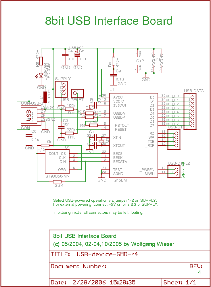
The objective was to create a compact USB interface board that can be easily connected to microcontroller boards. It is designed to support both USB-powered and externally-powered operation. The number of external components has been minimized, although there are...
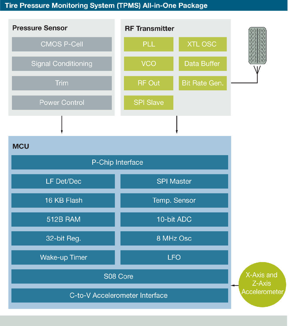
Freescale Semiconductor has introduced what it claims to be the industry's first tire pressure monitoring system (TPMS) featuring a capacitive pressure sensor designed for ultra-low power consumption and precise sensing. "By utilizing capacitive sensor technology, we achieve low power...
The schematic indicates that the AccelR8 utilizes only three integrated circuits (ICs). An AVR 8515 microcontroller performs the computational tasks and manages the other circuits. A MAX603 regulates voltage and controls the power-on and power-off functions. The key component...
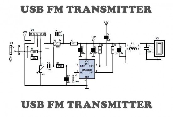
This is a simple USB FM transmitter designed to play audio files from an MP3 player or computer on a standard VHF FM radio. The USB FM transmitter operates by converting audio signals from a digital source, such as an...
A display tube utilizing a constant current circuit to ensure a steady flow through the tube. The display tube operates on the principle of maintaining a constant current to achieve consistent brightness and performance. The circuit typically comprises a current...
When configured as an input, there is a subtle issue. If the input has its pull-up enabled, it may interfere with the circuitry that expects to see an analog-to-digital (A/D) input. Conversely, if the pull-up is not enabled, the...