
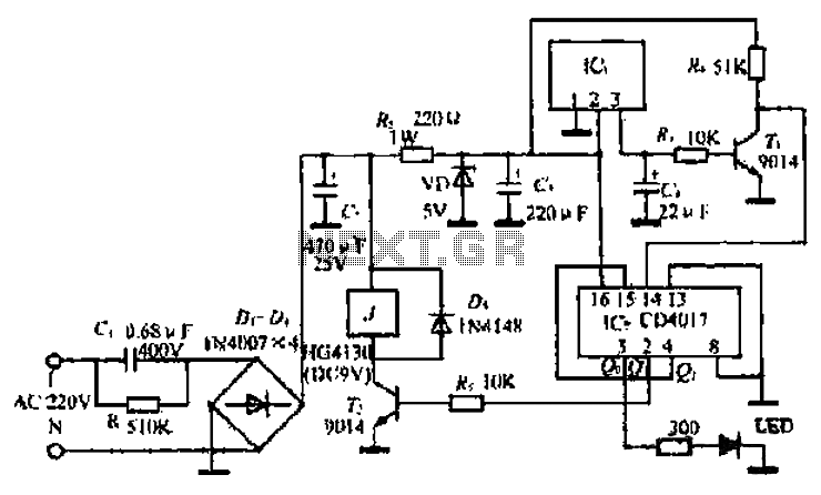
A simple remote control switch circuit
The ML4423 integrated controller is engineered to manage single-phase and two-phase AC induction motors effectively. This device utilizes PWM technology to facilitate precise speed control, thereby enhancing the operational efficiency of connected machinery. The controller incorporates several protective features, including short circuit protection and a fire protection circuit, ensuring safe and reliable performance in various applications.
The internal architecture of the ML4423 is defined by a series of functional pins, each serving a specific purpose. For instance, pins designated for differential input allow for voltage feedback from the motor coils, enabling real-time monitoring and adjustments to the motor's performance. The amplitude of the sine wave control voltage can be adjusted through specific input terminals, allowing for fine-tuning of motor operation at low speeds.
The ML4423 also includes output terminals for sine wave detection, which provide critical feedback on the motor winding signals. This feedback is essential for the PWM sine wave output signal, which drives the external power stage of the motor controller. The integration of these features allows the ML4423 to adapt the output voltage to align with an internal reference sine wave voltage, achieving optimal control over the motor's operation.
In terms of operational flexibility, the ML4423 supports both three-phase and two-phase motor configurations. The phase sequence control terminal enables the user to define the leading or lagging phase relationship, which is pivotal in applications requiring specific motor behaviors. The device also includes a reference voltage output and various resistive and capacitive connections to set PWM wave frequencies and other operational parameters.
The ML4423 is a comprehensive solution for applications requiring robust motor control, with its design emphasizing safety, adaptability, and efficiency in performance. The interconnected feedback loops and control mechanisms within the chip facilitate a seamless integration into broader motor control systems, making it a valuable component for engineers and designers in the field of electronics. Book mediated clam meaning of ML. 4423 © with integrated controller ii Liu t-phase and single-phase/two-phase AC induction motor built Organisation pretty machine control facil ities. M1,4423 LtlPWM cattle production, PWM controllers, the speed controller. Two sinusoidal crossing generator output short circuit protection and mountain driving. Limiting circuit. Guanidine fire protection circuit, 8V reference power supply circuit and the like. Internal structure diagram indiscriminately as I 67 (a) below.. chip pin functions: 1) foot (SENSE ] for the differential input .y:} Distorted foot (2) is connected to electrical machines AC coil voltage feedback pin (2) (SENSEc/Yes. C motor coil voltage feedback input. pins (3) (SENSEB) of the differential input, the foot (2) is connected to the motor winding for voltage feedback between BC.
foot (4) (VMIN) is the amplitude of the sine wave control voltage input terminal for low speed when adjusting the minimum amplitude sine wave. foot (5) (VSPEED) is SINEA and SINEB sinusoidal frequency and amplitude control terminal (voltage-controlled).
foot (6) (RSPEED) sine wave output current control terminal. sine current wave generator is proportional to the voltage pin. pin (7) (VREF) is 8V reference voltage output. feet (8) (RREF) setting resistor. feet (9) (RDT) for the output stage PWM frequency is dead time is set to prevent cross-conduction power tube (9 feet to a external resistor to achieve, the external resistor is 166kn, the dead zone time is 2 microseconds). foot (10) (SINEA) AC motor winding sine wave detection voltage output pin (11) (SINEB) is the output of the motor winding BC sinusoidal voltage detection.
feet (12) (C o) received sine wave frequency setting capacitance pin (13) (CPWM) connected PWM wave frequency setting given capacitor, the capacitor is connected with the end (8) pin RREF common with set PWM wave frequency. foot (14) (COAST) is a logic input, active low shutdown all the output transistor transistor. foot f 5) (F/R) is the phase sequence control terminal when the terminal is high, a phase leads B phase;.
humorous side is low. level, a phase lags phase B pin (16) (ISENSE) is the motor current detection input end, the terminal voltage of o.5v began limiting. foot (17) (GND) as common ground. feet (18) (3PH/2PH) is a three-phase/two-phase work to select the setting end, when the float three-phase motor drive, drive two-phase motor.
foot (19), when connected to Vcc (20), (21) (LB, LC, LA) is the low-end B, C, a-phase drive output. feet (22 ), (23), (24) (HB, HC, HA) are B, C, high drive output a phase. foot (25) for the SV/12V output driver selects the terminal, when the floating driver output 5v voltage, then when the driver output voltage of 12V Vcc. foot (26) (Vcc) is a power supply voltage lead-in terminal (+ 12V). (27), (28) feet (CGM, CGM2) connecting the feedback loop that set the poles capacitor. MLA43 basic application circuits. 1- 67 (b) as shown in the velocity output signal is applied, as shown in the chip inside the crossing of two sinusoidal amplitude and frequency changes, the motor winding signal through the motor coil, the pin (1) - foot (3) feedback to MLA423, chips PWM sine wave output signal to drive an external power pole, so that the anti- fed output voltage with an internal reference sine wave voltage to adapt, achieve the purpose of control.
Figure 1 - 67 (c) to ML4423 constitute the core of a complete three-phase motor controller schematic.
Related Circuits
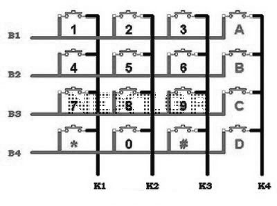
This includes an interface that is simple enough for mastery, as the keypad supports input facilities commonly used in Man-Machine Interface (MMI) applications. For example, various types of keypads can be found in the market. This discussion will focus...
This is a design circuit for a simple function generator. Built around a single 8038 waveform generator IC, this circuit produces sine, square, or triangle waves from 20Hz to 200kHz in four switched ranges. There are both high and...
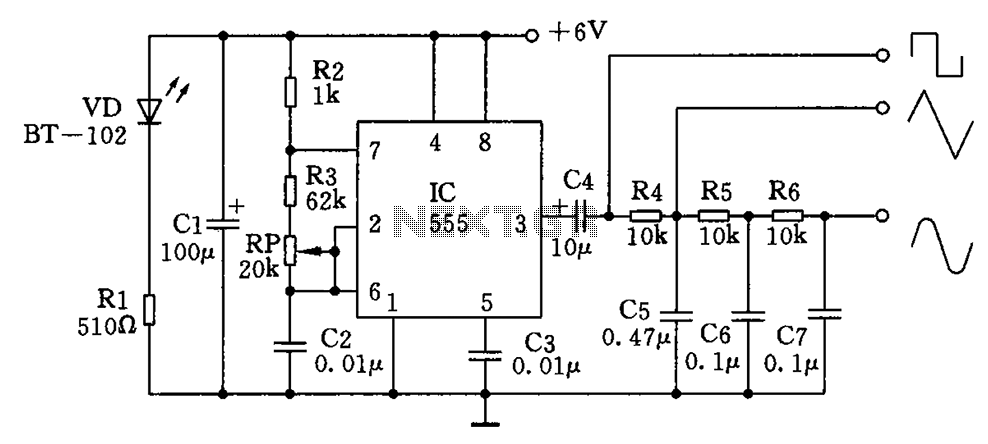
The circuit simultaneously generates a square wave, triangle wave, and sine wave, making it particularly suitable for electronics enthusiasts and students who wish to observe signal waveforms using an oscilloscope. This signal generator circuit is simple, low-cost, and allows...

FAN7710 Ballast Control circuit design for Compact Fluorescent Lamps electronic project. The FAN7710 is a specialized integrated circuit designed for the control of ballast systems in compact fluorescent lamps (CFLs). This circuit typically operates in a high-frequency range, facilitating efficient...
This SCADA controller is designed for use with distribution (13.2 kV/4.8 kV) substation transformer breaker positions where an automatic throw-over is present. The RTU voltage is 24V DC. The breaker status and lockout relays operate at 48V DC. The SCADA...
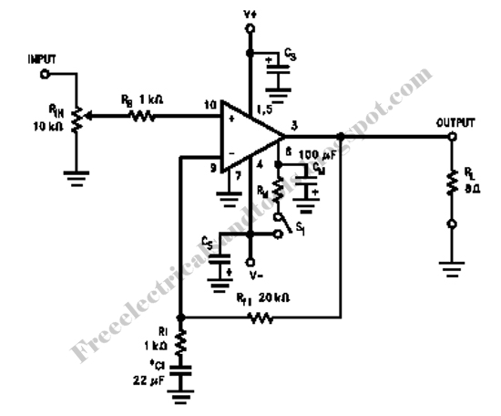
This simple LED tester consists of a current source with a potentiometer that can be used to adjust the current. The current source is implemented using a TL081 operational amplifier. The output current from the op-amp flows through the...
Warning: include(partials/cookie-banner.php): Failed to open stream: Permission denied in /var/www/html/nextgr/view-circuit.php on line 713
Warning: include(): Failed opening 'partials/cookie-banner.php' for inclusion (include_path='.:/usr/share/php') in /var/www/html/nextgr/view-circuit.php on line 713