
control keypad interfacing
The 4x4 keypad module is a matrix keypad consisting of 16 keys organized into 4 rows and 4 columns. Each key press connects a specific row to a specific column, allowing for easy identification of which key has been pressed. The operation of this keypad relies on a simple scanning technique implemented in the connected microcontroller. When the microcontroller scans the rows and columns, it sends a low signal to one column at a time while reading the states of the rows. If a button is pressed, the corresponding row will detect a low signal, indicating which key has been activated.
To prevent ghosting and ensure reliable operation when multiple keys are pressed, diodes can be added to each key in the matrix. This setup allows for the detection of multiple simultaneous key presses without erroneous readings. The schematic diagram of the keypad module will typically include connections for each button, the rows, and columns, as well as any necessary pull-up resistors to ensure stable readings.
In practical applications, the keypad can be interfaced with various microcontrollers, such as Arduino or PIC, using simple GPIO (General Purpose Input/Output) pins. The microcontroller's firmware will need to implement a debounce algorithm to filter out noise when a button is pressed, ensuring that only intentional presses are registered. Overall, the 4x4 keypad module is a versatile and widely used component in MMI applications, enabling user interaction in various electronic devices.This is including interface that is basic enough for we master, because key pad is supporting facilities for input which many applied in the application of MMI (Man Machine Interface). For example: There is many key pad types which able to be found marketing. We will take example of keypad module interface 4x4 that drawing the physical shown to th is figure; First Pace, we construction soybean cake of the hardware must, or minimum of the characteristic. Unknowingly construction hardware or characteristic a peripheral, we are not possible to be made interface program MCU to peripheral.
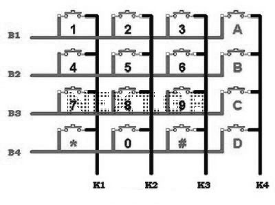
If you had known construction hardware and this module characteristic, please directly make a bolt for second steps. If it is disassemblied this module depth and depicted is its schematic diagram, hence us will get in this figure; There is 16 fruit of nipple pushbutton stringed up in such a way so becomes 4 column lane (K1, K2, K3, K4) and 4 battery lane (B1, B2, B3, B4).
From this construction, we can get the characteristic data is as follows: 2. There is no one condition enabling the happening of joint between column lane humanities or between battery lane humanities, except there are emphasis of nipple multiple. For example; nipple 1 and nipple 2 depressed to be at the same, hence K1-K2-B1 will be jointed. 3. For emphasis only one nipples, hence only happened joint between column lanes and battery lane that is connected at nipple depressed the.
For example, if nipple 1 is depressed, hence K1-B1 will be joint. Data as complete is for emphasis every nipple can be seen tables. Because at most application only be required detection to emphasis of one nipples only, so in the next will be studied handling to emphasis of one just nipples and disregards emphasis of nipple multiple. Flowchart work we are 🔗 External reference
Related Circuits
Nikon infrared remote control with special features for interval shots, multiple shots, and continuous shots. The Nikon infrared remote control is designed to enhance the photography experience by allowing users to capture images without physically touching the camera. This remote...

The primary objective is to present the circuit diagram and describe the software utilized. A UDP application is employed to transmit commands to the microcontroller, which subsequently activates or deactivates the relay. It is anticipated that TCP implementation could...
A USB solution is required for a project utilizing the LPC2148 microcontroller (MCU). In the past, interfaces such as LPT or COM were commonly used to connect projects to a PC, but these have become obsolete. The project allows...
A 4-position slide switch is utilized to activate different colored LEDs based on its position. Additionally, it is required to adjust the output frequency of a 555 timer operating in astable mode to drive a piezo buzzer. The challenge...
This circuit will allow you to connect any tape recorder that has a mic and remote input to a phone line and automatically record both sides of a conversation whenever the phone is in use. You will need to...

When a remote control fails to operate, the issue is often fundamental: the device does not emit light. Possible causes include dry solder joints, faulty LEDs, or a depleted battery, potentially due to a stuck button. The human eye...
Warning: include(partials/cookie-banner.php): Failed to open stream: Permission denied in /var/www/html/nextgr/view-circuit.php on line 713
Warning: include(): Failed opening 'partials/cookie-banner.php' for inclusion (include_path='.:/usr/share/php') in /var/www/html/nextgr/view-circuit.php on line 713