
a simple variable power supply circuit
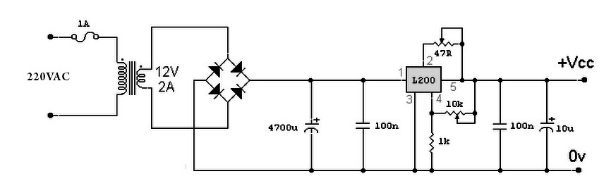
This variable power supply circuit utilizes the L200 integrated circuit, which is designed for adjustable voltage regulation. The L200 can provide a stable output voltage that can be finely tuned using a 10K potentiometer, allowing for a versatile range of applications. The output voltage can be adjusted between approximately 3V and 15V, making it suitable for powering various electronic devices that require different voltage levels.
The circuit operates by connecting the L200's output to the load, with the voltage adjustment achieved through the variable resistor. The potentiometer alters the feedback voltage to the L200, effectively changing the output voltage according to the user's requirements. The current output capability of the circuit ranges from a minimum of 10 mA to a maximum of 2 A, ensuring that it can handle a variety of loads without overheating or becoming unstable.
In terms of design, it is important to include appropriate filtering capacitors on both the input and output sides of the L200 to ensure stable operation and minimize voltage ripple. Additionally, heat dissipation should be considered, as the L200 can generate heat under load. A suitable heat sink may be required to maintain safe operating temperatures.
This variable power supply circuit is ideal for laboratory use, prototyping, and other applications where adjustable voltage and current are necessary. The simplicity of the design, combined with the flexibility of the L200 IC, makes it a valuable tool for engineers and hobbyists alike.Variable power supply based L200 for its output voltage is controlled by a variable resistor 10K. Output voltage range of values is from around 3 to 15 volts, and current range is about 10 mA minimum and a maximum of 2 amps. The schematic diagram come from circuit: A simple variable power supply circuit with L200 power supply.
Go to that page toread the explanation about above power supply related circuit diagram. 🔗 External reference
Related Circuits
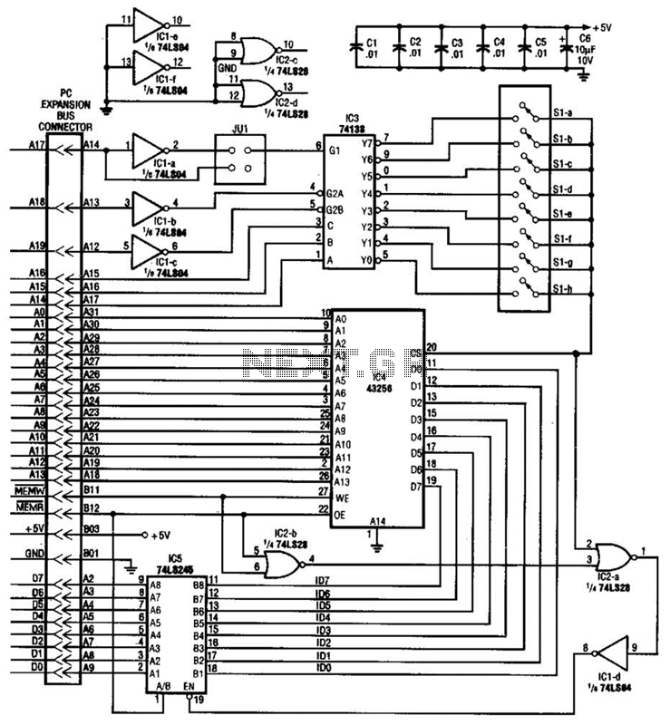
This circuit protects a PC by requiring a password to boot. After three unsuccessful attempts, the computer must undergo a cold reboot before the password can be attempted again. Software for this system is available; consult the reference for...
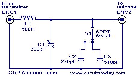
Low power (3 to 30 MHz) transmitters constructed by amateur radio operators are commonly referred to as QRP transmitters. A well-tuned antenna is essential for these transmitters; if the impedance is not properly matched, the output will be minimal...
This circuit utilizes the widely available LM3914 integrated circuit (IC). The IC is straightforward to operate, does not require external voltage regulators due to its built-in voltage regulation feature, and can be powered from nearly any voltage source. The LM3914...

When the lights of an oncoming car are detected by the photo-transistor Q1, the circuit activates. Sensitivity is adjusted by the 22-megohm resistor, R5, to approximately half a foot-candle. The relay employed has a 12-volt, 0.3A coil. The L14C1...
A bandpass filter allows a specific range of frequencies to pass while rejecting frequencies that fall outside the upper and lower limits of the passband. The frequencies that are permitted to pass are referred to as the passband, which...
The PR4403 is an advanced version of the PR4402 40mA LED driver. It features an additional input known as LS, which can be activated by pulling it low to illuminate the LED. This functionality simplifies the construction of an...