
Headlight circuit
The circuit operates by utilizing a photo-transistor (Q1) that responds to light levels. When the photo-transistor detects the illumination from an approaching vehicle's headlights, it triggers the circuit to activate a relay. The relay, rated for 12 volts and 0.3 amps, serves as a switch to control a higher power load, which may include lights or other devices.
The sensitivity of the photo-transistor is finely tuned by the 22-megohm resistor (R5), which defines the threshold light level required for activation. This resistor ensures that the circuit only responds to significant light levels, preventing false triggering from ambient light sources. The sensitivity is set to about half a foot-candle, a low level that allows the circuit to respond to the headlights of vehicles while ignoring other light sources.
The L14C1 component, which includes a lens with a one-inch diameter and a 10° viewing angle, aids in focusing the light onto the photo-transistor. This lens configuration helps to narrow the detection range, ensuring that the circuit is primarily responsive to light from directly in front, such as that from oncoming cars, rather than stray light from other directions.
In summary, this circuit is designed for effective light detection and control, utilizing a photo-transistor, a precision resistor for sensitivity adjustment, and a relay to manage the output load. The inclusion of a focused lens further enhances the performance of the light detection system, making it suitable for applications where reliable detection of vehicle headlights is essential.When the lights of an on-coming car are sensed by photo-transistor Ql, things get going. Sensitivity is set by the 22-megohm resistor, R5, to about half a foot-candle. The relay used has a 12-volt, 0.3A coil. The L14C1 is complete with a lens that has a diameter of one inch for a 10° viewing angle. 🔗 External reference
Related Circuits
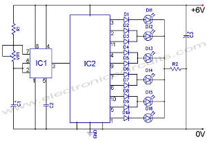
The following circuit illustrates an LED Knight Rider Circuit Diagram. This circuit is based on the 4017 and 555 integrated circuits. Features include the Knight Rider effect with four LEDs. The LED Knight Rider circuit is designed to create a...
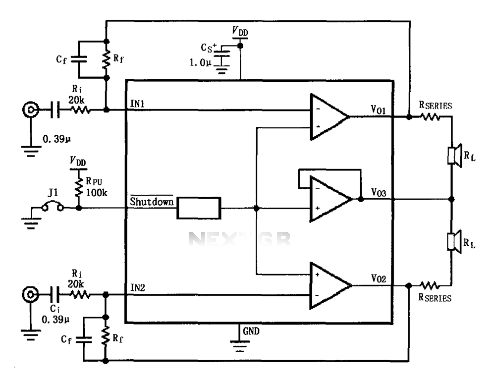
The circuit for the LM4910 is designed to minimize output noise and reduce power consumption. The output noise is attenuated by utilizing a resistor in series with the load. A feedback resistor Rf is used in conjunction with a...

The Tesla Coil will utilize a high voltage (HV) power source that outputs 9 kV at approximately 30 mA. The construction of the Tesla coil includes six glass bottles, table salt, oil, and aluminum foil for the capacitors. The...
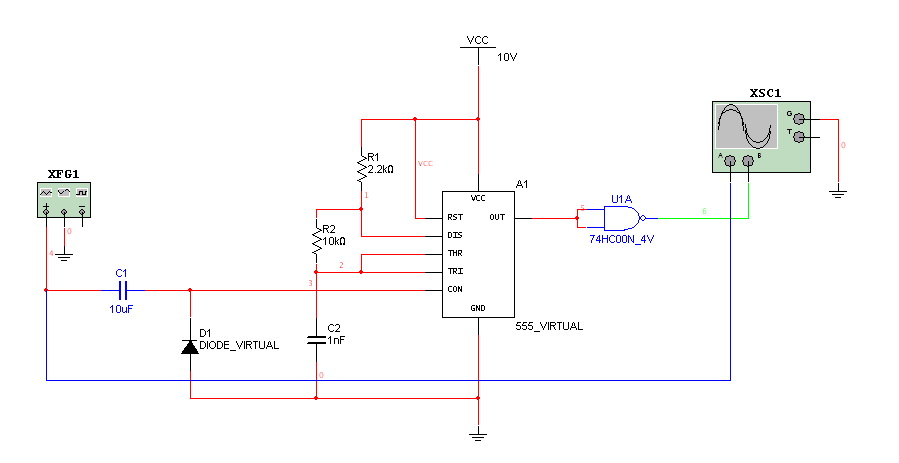
Hello everyone. I need some help. I have constructed a PWM and PPM circuit. The output is functioning smoothly, but I am experiencing some problems and I am not very experienced. The PWM (Pulse Width Modulation) and PPM (Pulse Position...

The device is a DC switch that remains normally on due to the forward biasing of Q1 through resistor R3. Q1 clamps Q2 into a forward state by biasing its complementary transistor well into saturation via resistor R4. The...
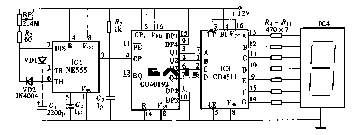
Digital timers feature a clear and precise display. They represent time intervals based on pulse signals, which are decoded by a digital device with a digital display unit. The circuit described pertains to a digital display for these timers,...