
Pc Password Protection Circuit
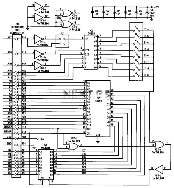
The described circuit functions as a security mechanism for personal computers, ensuring that unauthorized access is prevented during the boot process. The core of the circuit is a microcontroller or a dedicated security IC that monitors the input from a keypad or other input device where the password is entered.
Upon powering up, the circuit initializes and prompts the user for a password. The microcontroller compares the entered password against a pre-stored value in its non-volatile memory. If the correct password is entered, the circuit allows the PC to boot normally. In contrast, if the incorrect password is entered, the circuit increments a counter that tracks the number of failed attempts.
After three failed attempts, the circuit triggers a cold reboot of the PC, which can be achieved by controlling the power supply to the computer or by using a reset line. This mechanism ensures that the system is locked out temporarily, requiring the user to start the password entry process anew after the reboot.
The software component mentioned in the description is crucial for the configuration and management of the password system. It may provide functionalities such as setting the password, changing it, or even logging attempts for security auditing purposes. The software should be designed to interface seamlessly with the hardware, ensuring robust communication and minimal latency during the password verification process.
Overall, this circuit is an effective solution for enhancing the security of personal computers, particularly in environments where sensitive data is stored or accessed. With this circuit, a PC will be protected, requiring a password to boot. After three times, the computer will have to have a cold reboot and the password tried again. Software for this system is availableconsult the reference for further details. 🔗 External reference
Related Circuits
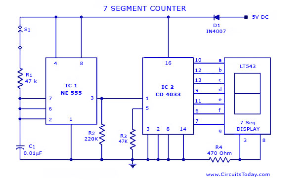
A simple seven-segment counter circuit with an LED display. This counter circuit diagram is designed using the IC CD 4033 as a counter, a 555 Timer IC, and a seven-segment LED display LT 543. The seven-segment counter circuit utilizes the...
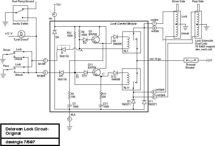
This document discusses the enhancement of a lock control module, providing instructions and photographs for upgrading the module to minimize its standby current consumption, thereby extending battery life. It is assumed that the user possesses a basic level of...
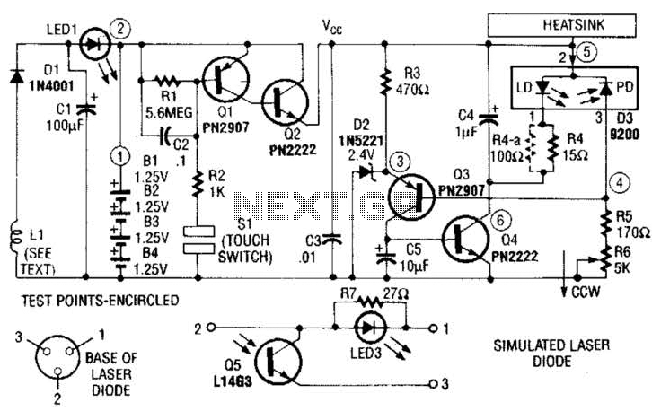
A laser diode TOLD9200 (Toshiba) serves as a source of laser light. Q3, Q2, and SI constitute a touch switch to control the laser. L1 is an RF pickup coil designed to extract energy from an RF-type battery charger....
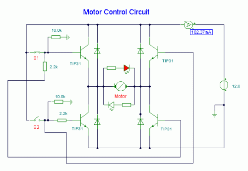
S1 and S2 are normally open, push-to-close, momentary switches. The diodes can be either red or green and are used solely for indicating direction. The TIP31 transistors may need to be adjusted based on the motor specifications. It is...
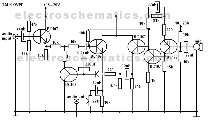
A very useful talk-over circuit that can be utilized in radio stations, clubs, or any location where speaking over music is desired without the need for adjusting a potentiometer. The talk-over circuit is designed to automatically reduce the volume of...
The circuit utilizes Q1 to buffer the right-channel balance output, while Q2 and Q3 create a VOX circuit. When the microphone signal level increases, the VOX output also rises, causing the multiplexer within IC1 to route the high-gain left-channel...