
Electronic Doorbell Circuit

The circuit design of the ding-dong electronic doorbell utilizes the IC 8021-2, which is specifically programmed to generate a pre-recorded sound sequence. The sound data is stored in a non-volatile format within the IC, enabling reliable playback each time the circuit is activated. The operation begins when pin 3 of the IC is pulled low, triggering the sound output.
To amplify the sound output, a complementary-pair, two-transistor amplifier is employed. This configuration ensures that the output signal is sufficiently strong to drive either a piezo tweeter or a standard 8-ohm speaker rated at 500mW. The choice of speaker affects the overall sound quality and volume, with the piezo tweeter typically providing a more compact solution, while the 8-ohm speaker may offer richer sound.
The circuit is designed to operate with minimal power consumption during standby, drawing only a few microamperes. This feature allows for the switch S1 to remain closed without significant battery drain, making the circuit efficient for prolonged use. The operation of the doorbell is initiated by pressing switch S2, which results in the ding-dong sound being played twice. Notably, if switch S2 is pressed again while the first sound is still being produced, it will have no effect on the ongoing playback, ensuring that the two sounds occur in succession without interruption.
Overall, the design emphasizes simplicity and cost-effectiveness, making it an ideal choice for a basic electronic doorbell application. Further testing and evaluation would be required to confirm performance and reliability in practical scenarios.This simple and cost-effective ding dong electronic doorbell circuit is based on IC 8021-2. The IC has an in-built circuitry to produce ding dong sound each time its pin 3 is pulled low. The sound is stored in the IC as bits, as in a ROM. The sound output from the IC can`t however drive a speaker directly, as this puts strain on the device. Theref ore a complementary-pair, two-transistor amplifier is used to amplify the sound to a fair level of audiblity. You may either use a piezo tweeter or an 8-ohm, 500mW speaker at the output. This simple electronic doorbell has not been tested. During the standby period, the IC consumes nominal current of a few microamperes only. Therefore switch S1 may be kept closed. Each time switch S2 is pressed, ding dong sound is produced twice. If you try to press switch S2 a second time when the first ding dong sound is still being produed, it has no effect whatever and the two ding-dong bell sounds will be invariably produced.
🔗 External reference
Related Circuits

A fade-in fade-out light switch enables gradual adjustments in lamp brightness, allowing the light to turn on and off smoothly. When the switch SA is closed, the lamp brightness increases from dim to bright. Conversely, when the switch SA...

A resistor R1, capacitor C1, and two converters create a square wave generator that produces a fundamental tone. This generator is followed by an inverter that functions as both a buffer and a driver for the system. Resistor R2,...
A telephone remote control system allows users to perform various functions remotely using their phone. This system automates complex tasks, simplifying the development and operation of telephone systems. The telephone remote control system is designed to enhance user interaction with...
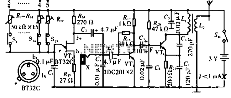
The circuit operates with VT3 and associated components arranged as a common-base capacitance feedback oscillation circuit. The oscillation frequency is set by capacitors C8, C9, and inductor L1. VT2 serves as a voltage amplification stage that reinjects the audio...
The diagram illustrates a human infrared remote sensing lamp circuit. It utilizes the trace infrared heat emitted by humans to control the lamp's operation, allowing it to turn on or off remotely. This human infrared remote sensing lamp features...
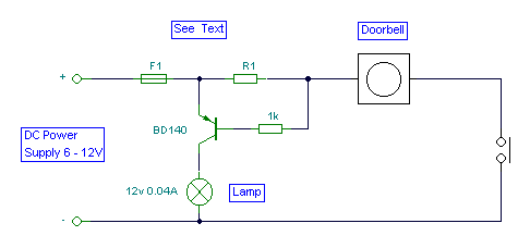
It is easy to miss the sound of a doorbell while watching TV. This circuit addresses the issue by providing a visual indication, such as a lamp or an LED. Connecting a lamp directly in parallel with the doorbell...