
A solar battery charger

The circuit operates as a battery management system for sealed lead-acid batteries, integrating a solar panel for energy harvesting. The primary components include a solar panel, a sealed lead-acid battery, a FET (Field Effect Transistor), and a comparator circuit utilizing the LM393 dual comparator. The FET serves as a switch that controls the charging process based on the battery voltage, while the LM393 comparators monitor the voltage levels.
The configuration of the comparators is crucial for the circuit's operation. The first comparator is set to monitor the battery voltage and will trigger the FET to stop charging when the voltage reaches a predetermined threshold, which is temperature compensated to adapt to varying environmental conditions. The second comparator monitors the discharge voltage and disconnects the load when the battery voltage falls below 11V. Once the voltage recovers to 12.5V, the load is reconnected, ensuring that the battery does not excessively discharge.
The design's effectiveness relies on the proper grounding of the comparators. Incorrect grounding can lead to unintended battery discharge through the solar panel, indicating that the circuit layout must be carefully considered to avoid ground loops or incorrect reference points.
Using micropower comparators like the TLC393 may lead to reliability issues, possibly due to differences in input voltage range or current handling capabilities compared to the LM393. The LM393 is more robust in this application, suggesting that the circuit's current and voltage characteristics are better suited to this component.
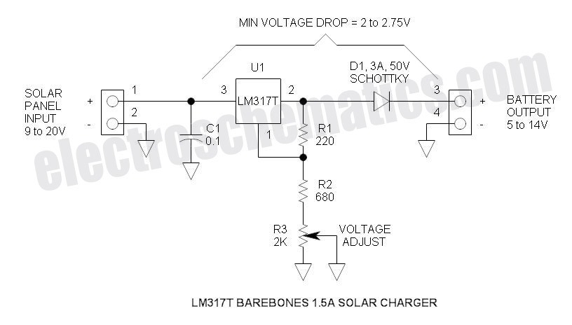
To enhance the design, a diode may be considered between the comparator inputs to prevent backflow of current, ensuring that the comparators function correctly without interference from the FET switching. Additionally, reviewing the component ratings and ensuring that all components are within their operational limits could improve reliability and performance. Overall, careful attention to component selection and circuit layout will be essential in achieving a stable and efficient charging system for sealed lead-acid batteries using solar energy.This circuit is intended for charging sealed lead-acid batteries with a solar panel in small and portable applications. The customary diode that prevents the battery from discharging through the solar panel has been replaced by a FET-comparator combination.
The charger will stop charging once a pre-set voltage (temperature compens ated) has been reached, and recommence charging when the voltage has dropped off sufficiently. The load is disconnected when the battery voltage drops below 11V and reconnected when it gets back to 12. 5V. If I ground the first two comparators (LM393) in the same place as the third, i. e. not between the FETs, the thing won`t work and the battery will discharge over the solar panel. Why Am I playing to close to the rails How can this be remedied/improved/redesigned Do I need a diode between the comparator`s imputs If I use micropower comparators like the Texas Instruments TLC393, the comparators blow up spectacularly, but with the standard LM393 everything works fine.
Why What did I miss 🔗 External reference
Related Circuits
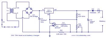
To set up the charging voltage, power on the charger and connect a voltmeter across the output terminals. Adjust R4 until the voltmeter reads 28V. The charger is now ready for battery connection. The charging circuit described involves a voltage...
This solar battery charger is a simple and cost-effective project suitable for hobbyists. While it has some limitations compared to other similar devices, it offers several advantages. The charger is designed for lead-acid batteries but can also charge any...
The TDA7088T can be used in mono portable and pocket radios. This is a bipolar integrated circuit. Here is one of the application circuit diagrams. The TDA7088T is a versatile bipolar integrated circuit designed specifically for mono FM radio applications,...
The Vx2SE is a simple discrete voltage-doubling SE for driving an LED. If the load is a red or green LED, J1 is used together with just one red or green LED for threshold detection (no 1381). For driving...
A close friend is interested in a dry cell lead-acid battery charger circuit designed for a 12V, 7.5Ah battery. The proposed model is simple and economical. The recommendation is to build this circuit using the highly popular LM317K integrated...
Nickel-Cadmium (NiCad) batteries serve as effective rechargeable power sources for portable devices. However, it is crucial to avoid damaging the batteries through overdischarge. Specifically, a NiCad battery should not be discharged to the extent that the cell polarity is...