
Solar Battery Charger Circuit

This solar battery charger circuit typically consists of the following components: a solar panel, an LM317T voltage regulator, a Schottky rectifier, a heat sink, and various passive components such as resistors and capacitors for voltage adjustment and filtering. The solar panel generates DC voltage, which is fed into the LM317T. The LM317T regulates the output voltage to the desired level, ensuring it is suitable for charging the battery. The Schottky rectifier is employed to rectify the voltage with minimal loss, allowing for efficient power transfer. The heat sink is crucial for dissipating heat generated by the LM317T during operation, ensuring reliable performance and preventing thermal shutdown. The circuit may also include a potentiometer for fine-tuning the output voltage, enabling the user to adjust the charging voltage according to the specific requirements of the battery being charged. Overall, this design offers a practical solution for hobbyists interested in solar energy applications.This is the most simple and affordable solar battery charger that the hobbyist can make. It has a few drawbacks over other similar controls, but offers numerous advantages. It is intended for charging lead-acid batteries, but may also be used for charging any battery at a constant voltage. Voltage output is adjustable. This is also referred to dro p-out voltage. The input voltage must exceed the output voltage by about 2. 75V @ 1. 5A. Fortunately, when the battery discharged, the output voltage is lower so the solar panel voltage will also be lower. When fully charged, the battery voltage will be high, but the current is very low ”at this point, the drop-out voltage reduces to about 2V and the open circuit solar panel voltage also comes into play.
The schottky rectifier was selected to reduce this head voltage requirement ”the voltage drop of the schottky is about 0. 5V @ 1. 5A or about half that of a typical silicon rectifier. In this solar battery charger project the power is limited by the thermal resistances of both the LM317T and the heat sink.
To keep the junction temperature below the 125 °C Max, the power must be limited to about 10W. If a smaller or less effective heat sink is used, the maximum power dissipation must be de-rated. Fortunately, the LM317 has internal temperature limiting so that if it gets too hot, it shuts down thus protecting itself from damage. Max power comes into effect when charging a 12V battery @ 1. 5A: e. g. battery voltage = 12V, solar panel = 18V. P = (18V 12V) * 1. 5A = 9W. So thermally, it is carefully matched to the current rating. If a solar panel that is characterized for 12V is applied with a 6V battery, the maximum current must be reduced to about 0.
7A: e. g. battery voltage = 6V, solar panel voltage = 18V. P = (18V 6V) * 0. 7A = 9. 6W. In this case, the solar panel power may not exceed 10W. When charging, the heat sink normally runs warm. When beginning to top off or completing the charge at maximum voltage, the heat sink runs hot. When fully charged, the heat sink runs cool. This heat is not exactly wasted power ”it is excess power that is unneeded in the process of charging a battery. Current limiting is provided by the solar panel ”it is not a commonly understood fact that the solar panel tends to be a constant current device.
For this reason, a solar panel can withstand a short circuit. This control charges the battery at a constant voltage and also maintains a charged battery (float charge). The float charge voltage specification is a little lower, so to accommodate both charge and float charge voltage, a compromise is reached by simply reducing the voltage slightly ”that is how ALL automotive systems operate.
To obtain maximum charge in a 12V battery, set the control to 14. 6V. Automotive systems further reduce voltage to 13 to 13. 5V in order to accommodate high temperature operation as the battery is usually located in the hot engine compartment ”battery has a negative thermal coefficient of voltage. It is difficult to determine how to set the voltage in this case. The easiest way to do this is to charge the battery fully using other means and then transfer the charged battery to the control and connect an ammeter in series.
Increase the voltage setting until there is significant current and then back off the potentiometer until the current drops to perhaps 10mA or so. Some types of batteries such as lithium ion types must be disconnected after charging to prevent degradation.
There is no protection against reverse polarity or mis-wiring. It is protected if solar panel is connected reverse without battery connected, or if battery is connected reverse without solar panel connected. However, if the battery or solar panel is misconnected simultaneously, who knows anyone care to experiment
🔗 External reference
Related Circuits

The inverting input is maintained at a low level via a 10K resistor when the circuit is powered on but not in use. During measurement activities, including calibration measurements where the input is floating, this resistor is disconnected. The...
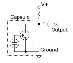
A simple circuit is desired that utilizes a microphone to capture voice and transmit the audio signal to a speaker. The objective is to understand the connections required for integrating a microphone into the circuit. To create a basic microphone-to-speaker...

To utilize this facility, the calling subscriber must first dial the standard phone number of the intended recipient. Once the call is connected, the calling party does not hear a ring-back tone. The calling subscriber must then press the...
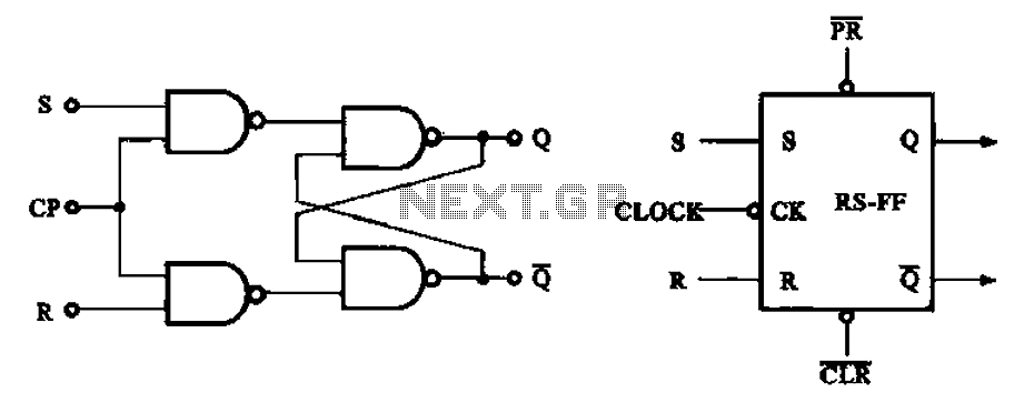
The asynchronous RS flip-flop mentioned earlier is not synchronized with the system clock signal. In contrast, the synchronous RS flip-flop incorporates synchronization, allowing it to operate in conjunction with the clock signal. Figure (a) illustrates the circuit configuration of...
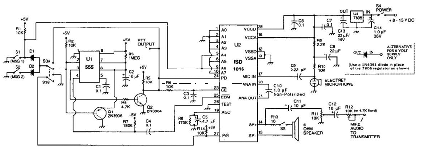
The circuit utilizes an ISD1016 audio record/playback chip from Information Storage Devices, Inc. to record and playback messages on demand. While it is primarily designed for use with transmitters, it can also serve as an electronic notepad or similar...
The LM317 is an adjustable, positive 3-terminal voltage regulator capable of supplying 100 mA (for RA87U control) or 1.5 A (for Order Code UF27E and N61CA) across an output voltage range of 1.2 V to 37 V. These voltage...