
24v lead acid battery charger diagram

The charging circuit described involves a voltage regulation mechanism to ensure that the output voltage is precisely set to 28V, which is typically required for charging specific types of batteries, such as lead-acid or lithium-ion batteries. The process begins with powering on the charger, which initiates the operation of the internal circuitry designed to manage the output voltage.
A voltmeter is utilized to monitor the output voltage across the charger’s terminals. This measurement is critical, as it provides real-time feedback on the voltage level being delivered. The adjustment of resistor R4 plays a pivotal role in calibrating the output voltage. R4 is likely part of a feedback loop or a voltage divider network that influences the voltage regulation circuit. By altering the resistance value of R4, the voltage can be fine-tuned until the desired output of 28V is achieved.
Once the voltmeter indicates that the output voltage is stable at 28V, the charger is deemed ready for use. At this point, batteries can be connected to the output terminals for charging. It is essential to ensure that the batteries are compatible with the 28V charging voltage to prevent damage or inefficiency during the charging process.
Safety precautions should be observed during this setup, including verifying the integrity of the charger and ensuring that connections are secure to prevent short circuits or other electrical hazards. Proper thermal management should also be considered, as charging can generate heat, which may require heat sinks or ventilation to maintain safe operating temperatures.To setup the charging voltage, power ON the charger and hook up a voltmeter across the output terminals and adjust R4 to make the voltmeter read 28V. Now the charger is ready and you can connect the batteries. 🔗 External reference
Related Circuits
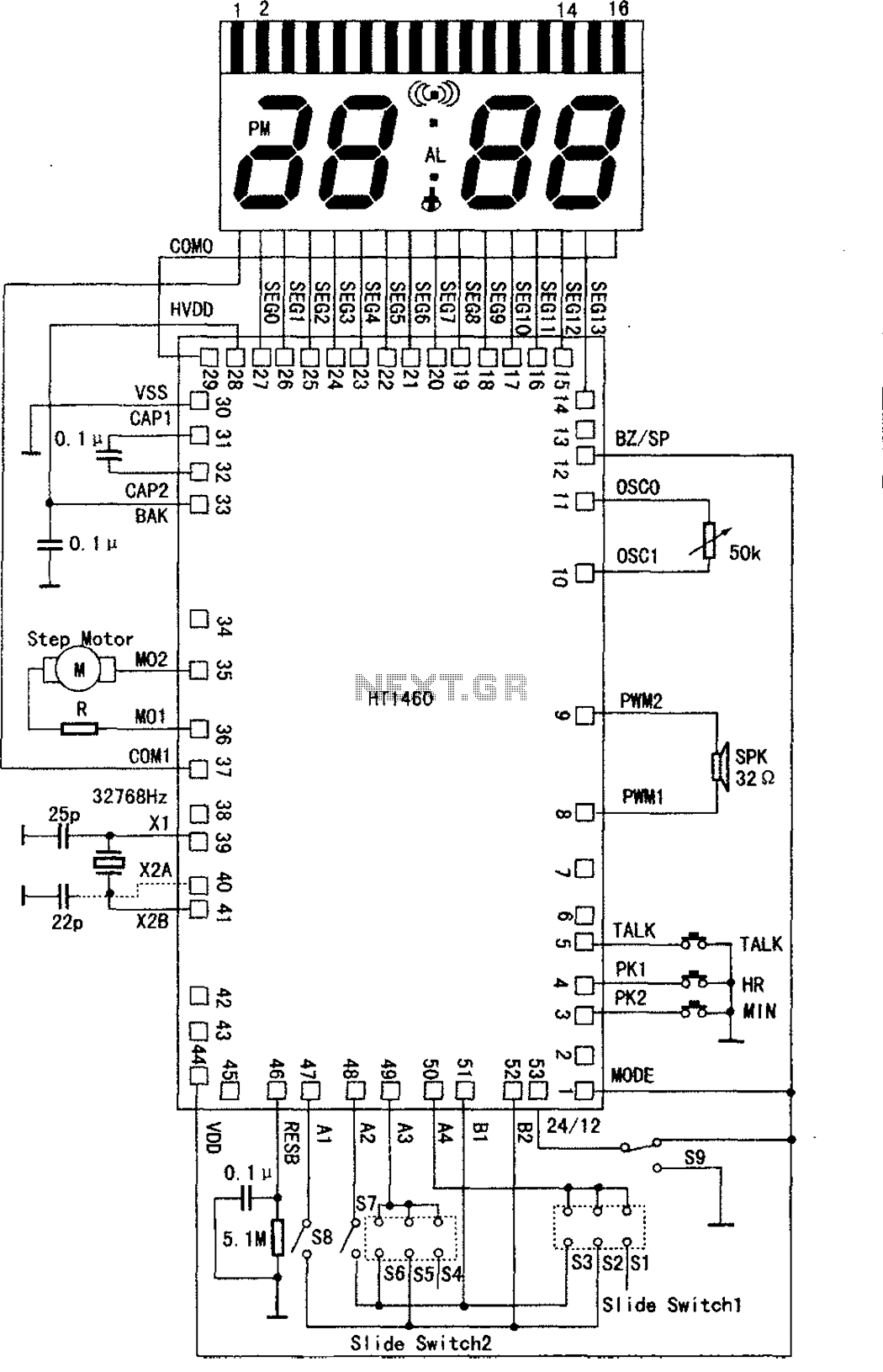
The speech synthesis circuit incorporates a microprocessor series, LCD drivers, a clock oscillator, input and output ports, memory, and a multi-voice audio signal amplifier circuit unit. This series circuit is primarily utilized in voice clocks, thermometers, electronic calendars, and...
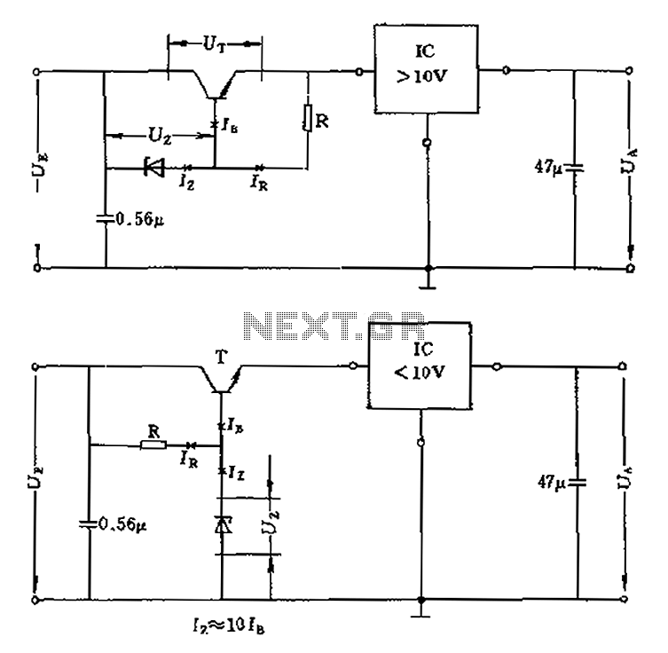
The voltage equation Ue = Ut + Ur + Ua indicates that the transistor voltage Ut will determine the maximum output voltage Ua. Additionally, Ur must be 2V. The voltage regulator's voltage value depends on the selection of Uz....
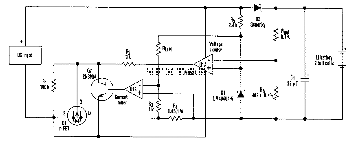
A universal rechargeable lithium battery circuit design, applicable to different battery types and numbers of batteries. This is because both the charger output voltage or current limit setpoint and the maximum charging current can be adjusted by simply changing...
Circuit for Grundig 5441 TV. If there are any issues related to this circuit, please provide additional information about the problem for further assistance. By accessing the Fixya site, users acknowledge that they have read and agreed to its...
This circuit utilizes the well-known and easily accessible LM3914 integrated circuit (IC). The IC is straightforward to operate, requiring no external voltage regulators due to its built-in voltage regulation capability, and can be powered by a variety of sources....
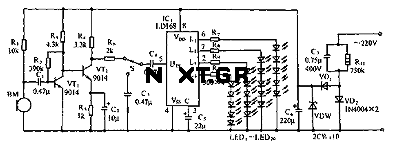
The circuit depicted in the figure involves the LD168, which functions as a sound level indicator for tape recorder speakers. It features four outputs capable of directly driving multiple light-emitting diodes. Additionally, the device can be activated by a...