
A Timer That Re-Triggers At Regular Intervals
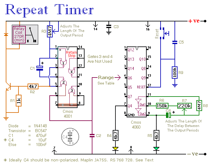
The CMOS 4060 is a 14-bit binary counter with an integrated oscillator. This oscillator is formed by two inverters connected to Pins 9, 10, and 11, with its frequency controlled by R7. The output from the oscillator is internally connected to the binary counter, which counts oscillations while the oscillator is active, with the count state reflected at the output pins. By adjusting R7, the duration for any given output pin to go high can be set. This output is connected to Pin 6 of the CMOS 4001, triggering the monostable each time it goes high. Ideally, capacitor C4 should be non-polarized; however, a standard electrolytic capacitor can be used as long as it does not leak significantly in the reverse direction. Alternatively, two 22 µF capacitors can be connected back to back to simulate a non-polarized 10 µF capacitor.
It is important to avoid using the on-board relay to switch mains voltage, as the board layout does not provide adequate isolation between the relay contacts and low-voltage components. For switching mains voltage, a suitably rated relay should be mounted safely away from the board. A single-pole, single-throw (SPST) or single-pole, double-throw (SPDT) relay can be utilized, with the option to use a multi-pole relay if desired.
To set up the timer accurately without relying on trial and error, a Setup Table can be employed to calculate the time required for Pin 7 of the CMOS 4060 to go high. For example, if the goal is to trigger the monostable every six hours, the Range Table indicates that Pin 1 of the CMOS 4060 should be used. This requires Pin 1 to go high every 21,600 seconds (6 hours). According to the Setup Table, this figure should be divided by 512, resulting in approximately 42 seconds. Adjust R7 so that the yellow LED illuminates 42 seconds after power is applied, which will cause Pin 1 to go high after about three hours. Pin 1 will remain high for three hours, then go low for three hours before going high again, resulting in a high signal every six hours. This high signal triggers the monostable, causing the relay to energize after an initial delay of three hours and subsequently re-energize every six hours thereafter.
During setup, the reset button should not be used, as the timing for Pin 7 to go high and the yellow LED to light must be measured from the moment power is applied. While resistors R4, R5, and the two LEDs assist in the setup process, they are not essential for the timer's operation. To reduce power consumption, these components can be disconnected after setup is complete. For increased LED brightness, brighter LEDs can be used, but caution should be taken not to reduce the values of the series resistors, particularly R5, as doing so may prevent the oscillator output from properly operating the counter. The timer is designed to operate with a 12-volt supply, but it can function within a range of 5 to 15 volts, provided that a suitable relay is employed. Powering the circuit initiates the timer, which can be reset at any time.This circuit has an adjustable output timer that will re-trigger at regular intervals. The output period can be anything from a fraction of a second to half-an-hour or more - and it can be made to recur at regular intervals of anything from seconds to days and beyond. The output section is a simple Monostable Circuit. When Pin 6 of the Cmos 4001 is taken high - the monostable triggers - and the relay energizes. It will remain energized for a period of time set by C1 & R3. With the values shown - R3 will provide output periods of up to about 30-minutes. However, you can choose component values to suit your requirements. For example, if you reduce R3 to 1meg - and C1 to 4. 7uF - the maximum output period is between 3 and 5 seconds. Owing to manufacturing tolerances - the precise length of the time period available depend on the characteristics of the actual components you`ve used. The Cmos 4060 is a 14-bit binary counter with a built-in oscillator. The oscillator consists of the two inverters connected to Pins 9, 10 & 11 - and its frequency is controlled by R7.
The output from the oscillator is connected internally to the binary counter. While the oscillator is running - the IC counts the number of oscillations - and the state of the count is reflected in the output pins. By adjusting R7 - you can set the length of time it takes for any given output pin to go high. Connect that output to Pin 6 of the Cmos 4001 and - every time it goes high - it`ll trigger the monostable.
Ideally C4 should be non-polarized - but a regular electrolytic will work - provided it doesn`t leak too badly in the reverse direction. Alternatively - you can simulate a non-polarized 10uF capacitor by connecting two 22uF capacitors back to back - as shown.
Do not use the "on-board" relay to switch mains voltage. The board`s layout does not offer sufficient isolation between the relay contacts and the low-voltage components. If you want to switch mains voltage - mount a suitably rated relay somewhere safe - Away From The Board.
I`ve used a SPCO/SPDT relay - but you can use a multi-pole relay if you wish. Since the delays between outputs can last for hours - or even days - using "Trial and Error" to set-up the timer would be very tedious. A better solution is to use the Setup Table provided - and calculate the time required for Pin 7 of the Cmos 4060 to go high.
For example, if you want the monostable to trigger every Six Hours - the Range Table tells you to use Pin 1 of the Cmos 4060. You need Pin 1 to go high every 6 x 60 x 60 = 21 600 seconds. The Setup table tells you that for Pin 1 you should divide this figure by 512 - giving about 42 seconds.
Adjust R7 so that the Yellow LED lights 42 seconds after power is applied. This will cause Pin 1 to go high after about 3 Hours. When Pin 1 goes high it will stay high for three hours. It will then go low for three hours - before going high once again. Thus, Pin 1 goes high once every six hours. It`s the act of going high that triggers the monostable. So - after an initial delay of three hours - the relay will energize. It will then re-energize every six hours thereafter. The reset button should NOT be used during setup. The time it takes for Pin 7 to go high - and the Yellow LED to light - MUST be measured from the moment power is applied. Although R4, R5 and the two LEDs help with the setup - they are not necessary to the operation of the timer.
If you want to reduce the power consumption - disconnect them once you`ve completed the setup. If you want the LEDs to glow brighter - use brighter LEDs. Don`t be tempted to reduce the values of the series resistors - especially R5. If you reduce its value too far - the oscillator output will not operate the counter. The timer is designed for a 12-volt supply. However - provided a suitable relay is used - it will work at anything from 5 to 15-volts. Applying power starts the timer. It can be reset at any time 🔗 External reference
Related Circuits
A programmable clock timer circuit that utilizes individual LEDs to indicate hours and minutes. Twelve LEDs can be arranged in a circle to represent the twelve hours of a clock face, while an additional twelve LEDs can be arranged...
Telephones are declining globally; however, India has over 350 million mobile phone users, alongside a significant number of traditional telephone users. This telephone timer is designed to save costs by controlling unnecessary time spent during phone calls. This simple...
The 555 timer IC was first introduced around 1971 by the Signetics Corporation as the SE555/NE555 and was referred to as "The IC Time Machine." It was the first commercially available timer IC, providing circuit designers and hobbyists with...
The purpose of this circuit is to power a lamp or other appliance for a specified duration (30 minutes in this case) and then automatically turn it off. This functionality is particularly useful for reading in bed at night,...
Figure 1-1 illustrates a general-purpose timer capable of timing intervals ranging from 5 minutes to 18 hours. The timing cycle can be adjusted to span from 5 minutes to 20 hours, with a maximum control time of 18 hours....
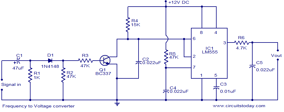
A simple frequency to voltage (F to V) converter circuit utilizing the LM555 Timer IC. This circuit has numerous applications in digital frequency meters, tachometers, and other related devices. The frequency to voltage (F to V) converter is a crucial...