
WIEN BRIDGE OSCILLATOR CIRCUIT
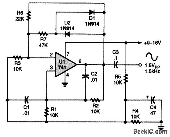
The Wien-bridge oscillator is a type of electronic oscillator that generates sine waves. In this configuration, the 741 op-amp serves as the active gain element, providing the necessary amplification to sustain oscillations. The circuit's feedback loop is formed by the resistors R1 and R2, and the capacitors C1 and C2, which create a frequency-selective network.
The frequency of oscillation, \( f \), can be determined through the formula:
\[
f = \frac{1}{2\pi R \sqrt{C1 \cdot C2}}
\]
where \( R \) is the equivalent resistance, which, in the case of a dual-gang potentiometer, can be adjusted to vary the resistance in the circuit. The values of C1 and C2 must be matched to ensure stable oscillation.
NPO (Negative Temperature Coefficient) capacitors are chosen for their minimal drift with temperature changes, which contributes to the overall stability of the oscillator. Metal-film resistors are selected for their low noise and high precision, further enhancing the performance of the circuit in audio applications.
To convert this fixed-frequency oscillator into a tunable version, the dual-gang linear potentiometer allows for simultaneous adjustment of both R1 and R2, enabling the user to fine-tune the frequency output. This flexibility makes the circuit suitable for a wide range of audio applications, including synthesizers, tone generators, and other audio processing devices.
When selecting capacitors C1 and C2, it is important to consider the desired frequency range. Larger capacitance values will lower the frequency of oscillation, while smaller capacitance values will increase the frequency. This tunability can be particularly useful in applications where precise frequency control is required, such as in musical instrument design or audio testing equipment.
Overall, the Wien-bridge oscillator utilizing a 741 op-amp is a robust solution for generating stable sine wave signals, with the potential for customization to meet specific frequency requirements.A 741 op amp is connected to a Wien-bridge, audio-sine-wave oscillator configuration, with C1, C2, R1, and R2 determining the circuit`s operating frequency. With the use of NPO capacitors and metal-film resistors, the oscillator`s frequency is stable enough for use in tone-control applications.
The fixed-frequency oscillator shown can easily be co nverted into a tunable oscillator by substituting a dual-gang linear potentiometer for R1 and R2. Different frequency ranges can be covered by using other matched values for C1 and C2. Larger values produce lower frequencies, and vice versa for small values. 🔗 External reference
Related Circuits
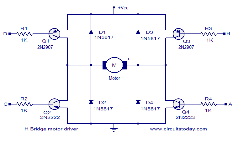
The circuit presented is a simple H-bridge motor driver circuit utilizing commonly available components. An H-bridge is an efficient method for driving motors and is widely used in various electronic projects, particularly in robotics. The circuit illustrated is a...
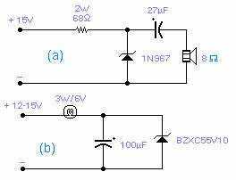
These two circuits are interesting from an academic point of view. Their practical implementation is rather critical and it is not easy to get steady operation. Circuit (a) requires a "cooked" zener: connect it first to a constant current...
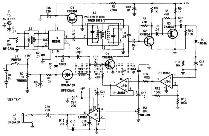
The integrated circuit Ul (an NE602 double-balanced mixer) functions as both an oscillator and a frequency mixer. Signals from the antenna input (at Jl) are transmitted through a DC-blocking capacitor C1 to the RF gain control, Rl, and subsequently...
This audio noise filter circuit is a bandpass filter designed for the audio frequency range. It effectively filters out unwanted signals that fall below or above the audio frequency spectrum. The audio noise filter circuit operates as a bandpass filter,...
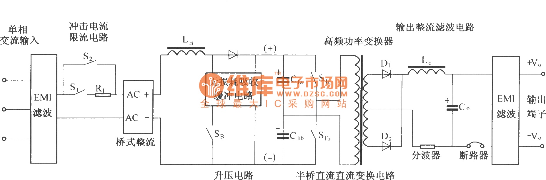
The figure illustrates a simplified schematic diagram of the main circuit DMA12. It primarily consists of the input circuit, an electromagnetic interference (EMI) filter circuit, an impulse current limit circuit, an input rectifier filter circuit, a boost/power factor correction...
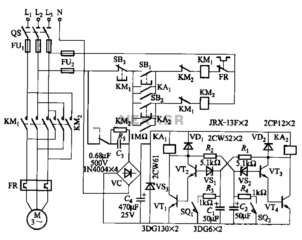
The circuit illustrated in Figure 3-72 employs a deformable bistable reversing motor control mechanism that automatically initiates and halts operation during a user-defined time delay. This feature is designed to safeguard the motor from potential impacts during the reversing...
Warning: include(partials/cookie-banner.php): Failed to open stream: Permission denied in /var/www/html/nextgr/view-circuit.php on line 713
Warning: include(): Failed opening 'partials/cookie-banner.php' for inclusion (include_path='.:/usr/share/php') in /var/www/html/nextgr/view-circuit.php on line 713