
Stereo Preamplifier Circuit (741)
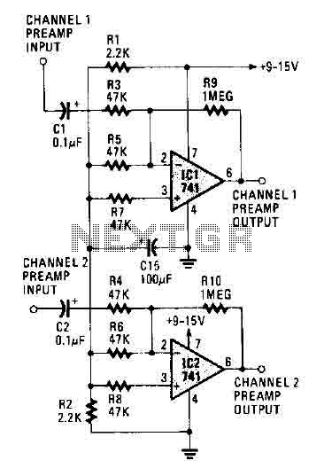
This circuit design employs two 741 operational amplifiers configured in a non-inverting amplifier arrangement. Each op-amp amplifies the input signal, providing a substantial gain of over 20 dB per channel, which is suitable for a variety of audio applications. The choice of the 741 op-amp, while adequate for many purposes, can be enhanced by selecting a higher-performance op-amp. This substitution would yield improvements in both the noise figure and bandwidth, resulting in clearer audio output and a wider frequency response.
The circuit exhibits a sharp roll-off at 20,000 Hertz, indicating that frequencies above this threshold are significantly attenuated. This characteristic is crucial in audio applications, as it helps to eliminate unwanted high-frequency noise and interference, thereby enhancing the overall sound quality. The roll-off is typically achieved through the use of passive components such as capacitors and resistors in conjunction with the op-amps, which dictate the cutoff frequency and slope of attenuation.
In summary, this circuit is a fundamental audio amplifier design that can be optimized for better performance through the careful selection of op-amps and the design of the frequency response characteristics. The combination of these elements allows for effective amplification while maintaining sound fidelity across the desired frequency range.The circuit works with two 741 opamps and provides better than 20 dB gain in each channel. A better type op-amp will give a better noise figure and bandwidth. In this circuit, the sharp roll-off is at 20,000 Hertz. 🔗 External reference
Related Circuits

This device offers numerous implementation possibilities due to its wide input voltage range and large maximum output current across a broad output voltage spectrum. It features long battery life and low power consumption owing to its high efficiency and...
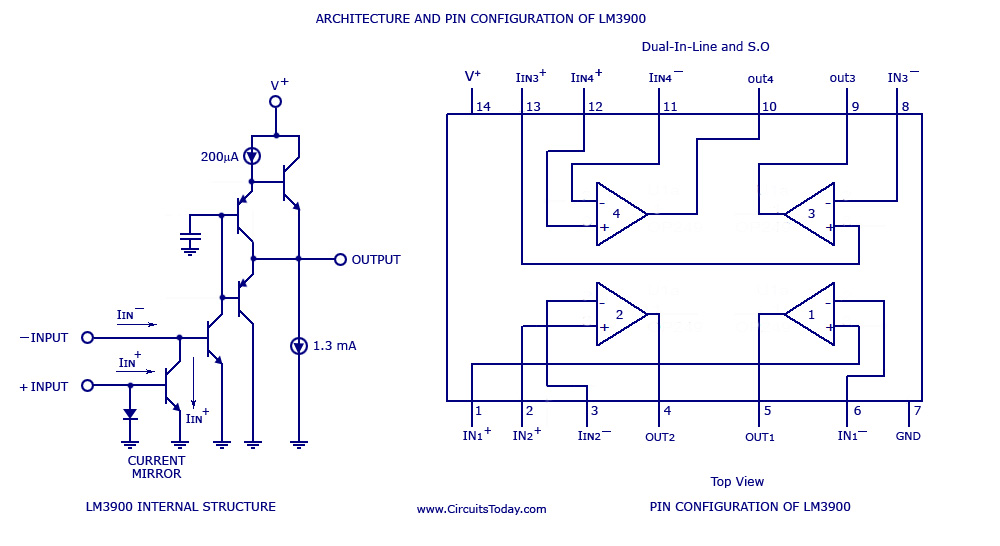
A simple multi-channel audio mixer circuit utilizing the LM3900 quad amplifier is presented below. The circuit features a four-channel quad amplifier (LM3900) with two microphone audio inputs and two direct line inputs. By paralleling additional circuits, the number of...
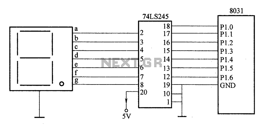
After the SCM execution, the Pl output port connects to the bidirectional input of 74LS245 driver chips. This driver operates during each phase of digital control, based on the information from the Pl port. The purpose is to convert...
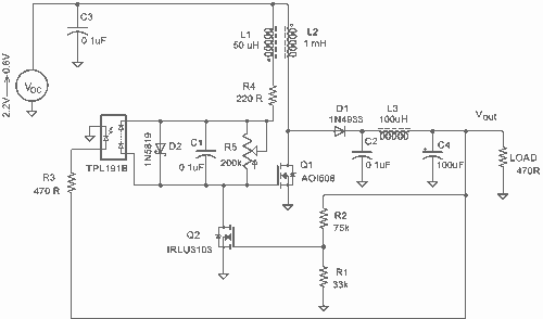
It employs a low threshold MOSFET and two coupled coils to function as a joule thief. An additional MOSFET is utilized for regulation. The circuit operates as a joule thief, which is a type of DC-DC converter designed to extract...
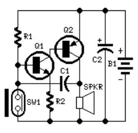
The system involves positioning a small magnet near the stalk switch SW1, which is connected to the hand or garments of the individual carrying the bag via a tiny cable. Due to the compact nature of the circuit, it...
This is an FSK modulation circuit composed of the 74LS74. The FSK modulation circuit does not include a phase-locked loop (PLL) or a high-Q bandpass filter, eliminating the need for tuning adjustments in the high-frequency modulation circuit. The two...
Warning: include(partials/cookie-banner.php): Failed to open stream: Permission denied in /var/www/html/nextgr/view-circuit.php on line 713
Warning: include(): Failed opening 'partials/cookie-banner.php' for inclusion (include_path='.:/usr/share/php') in /var/www/html/nextgr/view-circuit.php on line 713