
A wide range of 7 ~ 40V turn 5VDC-DC step-down circuit diagram

This circuit operates as a buck converter, designed to efficiently reduce a higher DC voltage (ranging from 7V to 40V) to a stable output of 5V. The primary components of the circuit include a switching element (typically a MOSFET), an inductor, a diode, and a capacitor.
The operation begins when the MOSFET is turned on, allowing current to flow through the inductor. As the current increases, energy is stored in the magnetic field of the inductor. When the MOSFET turns off, the inductor releases its stored energy through the diode to the output capacitor and load. The output voltage is regulated by adjusting the duty cycle of the MOSFET, which is controlled by a feedback loop. This feedback loop monitors the output voltage and adjusts the switching frequency to maintain the desired 5V output, even with variations in input voltage or load conditions.
Key specifications for the circuit design include the selection of the inductor, which must be rated for the maximum current expected in the application, and the output capacitor, which should have a low equivalent series resistance (ESR) to minimize voltage ripple. Additionally, the diode should be a Schottky type to ensure fast switching and reduce power losses during the operation.
The circuit can be further enhanced with features such as overvoltage protection, thermal shutdown, and soft-start mechanisms to improve reliability and performance in various applications, including powering microcontrollers, sensors, and other low-voltage devices.A wide range of 7 ~ 40V turn 5VDC-DC step-down circuit is as follows:
Related Circuits
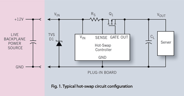
To ensure reliability, the server system designer must take into account the parasitics of hot-swap circuits and their associated transient behavior. It is recommended that a transient voltage suppressor (TVS) diode clamp be utilized at the line card input....
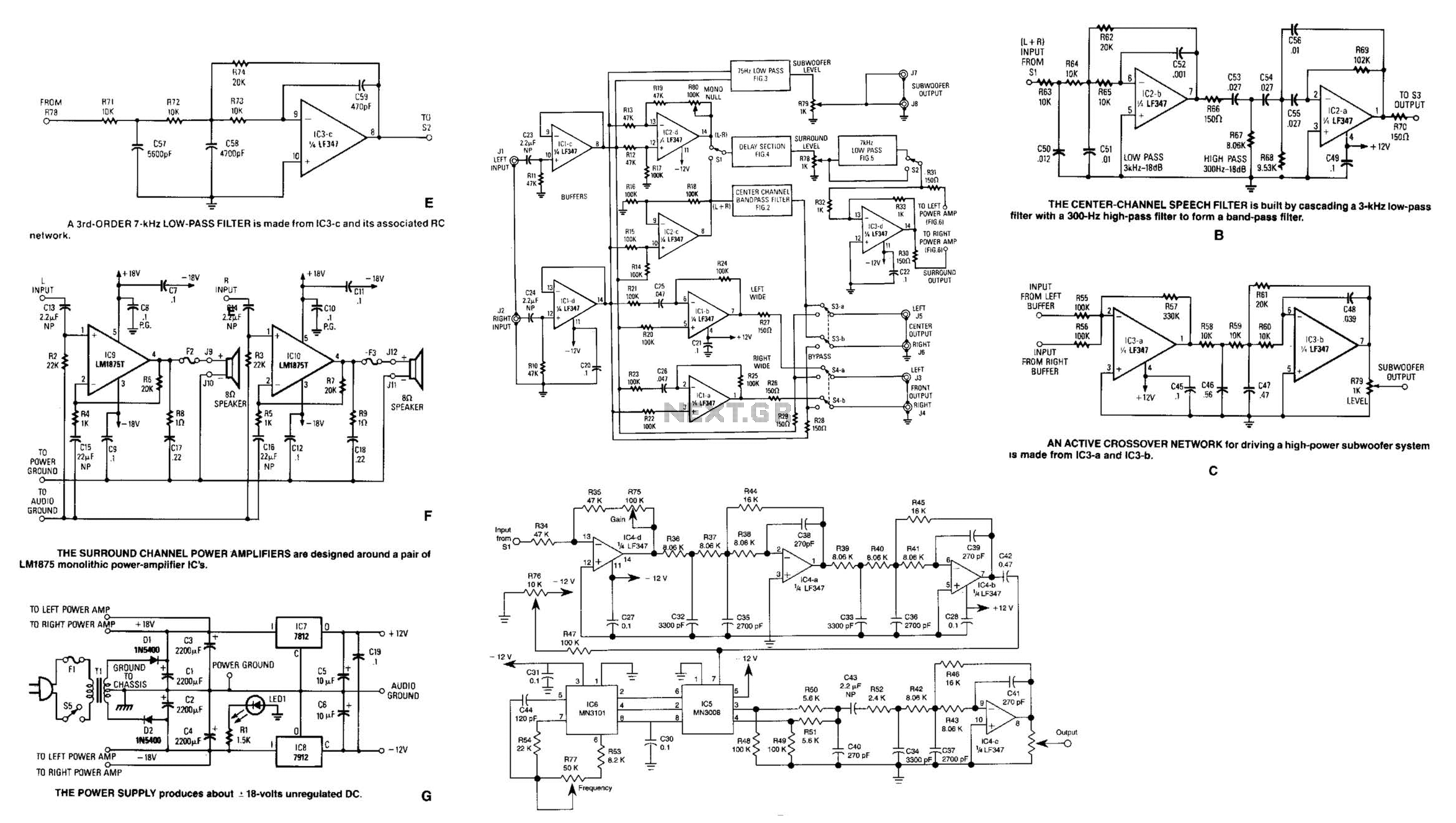
Referring to the simplified schematic in A, the audio frequency generator (AFG) consists of 10 relatively simple circuit elements. IC1-c and IC1-d are configured as unity-gain non-inverting buffer amplifiers. The summing amplifier, IC2-c, combines equal amounts of the left...
The oscillation circuit of the transmitter was added. An oscillation circuit using a 555 IC is implemented for a modified circuit. This allows for easy adjustment of the oscillation frequency, necessitating changes to the software. The described circuit employs the...
The voltage regulator is an LM317T, and should accept up to about 14 volts without problems. It can handle up to 1 amp, but you WILL need a heatsink on the voltage regulator. I also added DC power jacks...
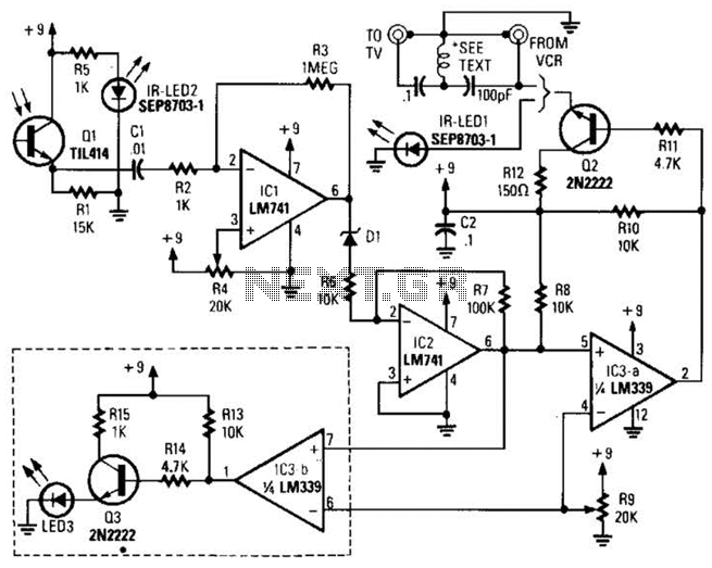
A signal from an infrared (IR) remote control is converted from IR radiation to a frequency pulse that can be transmitted through coaxial TV cable or any other two-conductor wire to another room, where it is converted back into...
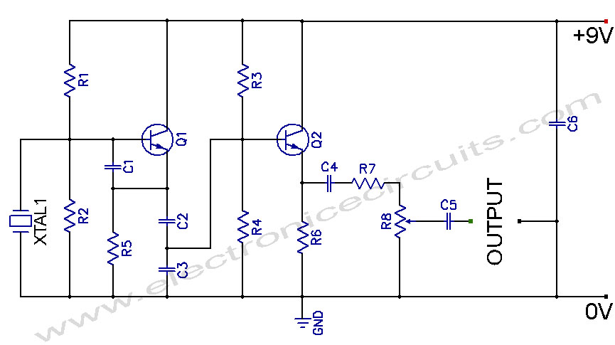
Crystal Controlled Oscillator Circuit. This general-purpose signal source is highly effective in signal-tracing applications. The output level is adjustable. The crystal-controlled oscillator circuit is designed to provide a stable and precise frequency output, which is essential for various electronic applications,...