
EAGLE Ultrasonic Range Meter

The described circuit employs the 555 timer IC, a versatile and widely used component in various electronic applications. The 555 timer can function in different modes, including astable, monostable, and bistable configurations. In this context, it is utilized in astable mode to generate a continuous square wave output, which serves as the oscillation signal for the transmitter.
In the astable configuration, the 555 timer produces an oscillation frequency determined by the values of two resistors (R1 and R2) and a capacitor (C1) connected to its pins. The frequency (f) of the oscillation can be calculated using the formula:
f = 1.44 / ((R1 + 2*R2) * C1)
This equation illustrates that by varying R1, R2, or C1, the oscillation frequency can be adjusted to meet the specific requirements of the transmitter. The output frequency can be fine-tuned to ensure optimal performance, which is crucial for applications such as wireless communication, where precise frequency control is necessary.
The integration of the 555 timer circuit into the transmitter design necessitates corresponding adjustments in the software that governs the transmitter's operation. The software must account for the newly introduced oscillation frequency to maintain synchronization and functionality. This may involve recalibrating frequency settings, updating modulation schemes, or implementing additional control algorithms.
In summary, the incorporation of a 555 IC oscillation circuit into the transmitter design enhances frequency adjustability, thereby improving the overall performance and flexibility of the system. The changes in software are essential to fully leverage the benefits of the modified circuit, ensuring seamless operation and reliability in transmitting signals.The oscillation circuit of the transmitter was added. An oscillation circuit by 555 IC is used for a modified circuit. This is to adjust an oscillation frequency easily. Thereby, it is necessary to change the software. 🔗 External reference
Related Circuits

The thermistor RT, along with resistors R1, R2, R3, and variable resistor RP1, creates a temperature measurement bridge. At a temperature of 20°C, the configuration of R1, R3, and the adjustment of RP1 enables the bridge to maintain balance....
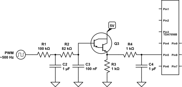
A voltage between 0.4 and 1.2 V is required on pin 5 to control the gain. In the initial two versions of the circuit, logic ICs and/or counters were utilized along with an operational amplifier and a resistor network...
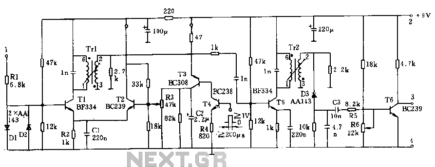
The circuit operates at a voltage of 9V with a current consumption of only 5mA. It allows for frequency adjustment within the range of 150 to 180 kHz, featuring a bandwidth of approximately 20 kHz. This configuration ensures that...
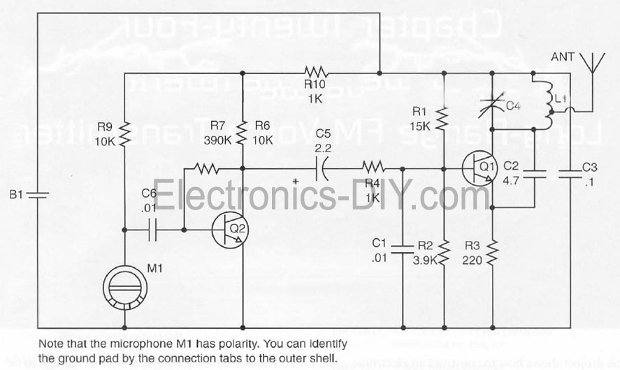
This document presents a Long Range FM Transmitter circuit, which is a highly sensitive, low-power FM transmitter. It includes a radio frequency (RF) oscillator section connected to a high-sensitivity, wide pass-band audio amplifier and a capacitance microphone equipped with...
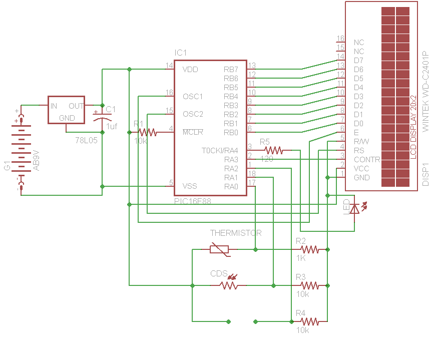
The initial concept for this project involves interfacing the WINTEK WD-C2401P LCD panel with a PIC microcontroller. The intention is to incorporate several ADC readings to provide useful information on the LCD. PORTB on the PIC serves as the...
This sound level meter circuit can be used to control the intensity of a sound recording or in a disco. It has 5 measurement domains between 70 and 120 dB. The sound level meter circuit is designed to measure sound...