
LM317 Regulator Circuit
The LM317T voltage regulator is a versatile and widely used component in electronic circuits, capable of providing a stable output voltage with a maximum output current of 1 amp. It operates with an input voltage range typically up to 14 volts, making it suitable for various applications, including powering low-voltage devices.
In the described circuit, the LM317T is configured with appropriate resistors to set the desired output voltage. The output voltage can be adjusted by changing the resistor values connected to the adjustment pin of the LM317T. This allows for flexibility in powering devices that require different voltage levels. However, if the circuit is intended for devices that operate at a single voltage, the adjustable feature may be unnecessary.
To ensure reliable operation, a heatsink is mandatory for the LM317T, as it dissipates heat generated during voltage regulation, especially when the input voltage is significantly higher than the output voltage. The heatsink should be appropriately sized to maintain the regulator's temperature within safe limits during operation.
The circuit includes DC power jacks for both input and output connections, facilitating easy integration into various setups. The incorporation of a green power LED serves as a power indicator, illuminating when the circuit is powered on. Additionally, a red over-voltage LED is included to provide a visual alert if the output voltage exceeds a predetermined threshold. This LED is controlled by a zener diode, which is selected based on the specific voltage level required for activation; in this case, a 6.2V zener diode is utilized.
The zener diode's breakdown voltage can be adjusted by selecting a different zener, allowing for customization of the over-voltage protection feature. This is particularly beneficial for safeguarding sensitive electronic components from damage due to excessive voltage.
Overall, this voltage regulator circuit is designed for practicality and efficiency, providing essential features for voltage regulation while ensuring user safety through visual indicators and over-voltage protection.The voltage regulator is an LM317T, and should accept up to about 14 volts without problems. It can handle up to 1 amp, but you WILL need a heatsink on the voltage regulator. I also added DC power jacks for input and output on my voltage regulator, a green power LED, and a red over-voltage LED. The over voltage LED uses a zener diode to switch on the LED at a certain preset voltage, this can be varied depending on the voltage of the zener diode, I used a 6.2v zener diode.
If you plan to vary the voltage for the different items you power, don`t bother adding this feature. If you only plan to use items that run on one voltage, this is a very useful feature and will save plugging in and damaging your valuable (or not so 🔗 External reference
Related Circuits
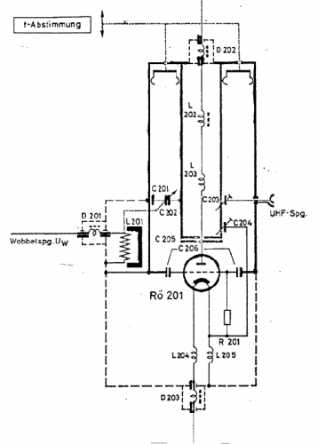
The use of a quarter-wave parallel-wire line as a tuning unit has been discussed in the chapter on Short Lines, where it was pointed out that these circuits have comparatively high Q even at higher frequencies. Their great length...
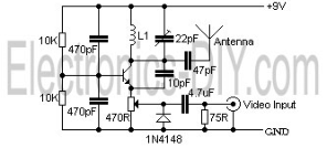
The video transmissions from this unit can be received on a small portable, tunable, and battery-operated TV set, similar to those found in flea markets. The described unit is capable of transmitting video signals that can be captured by compact,...
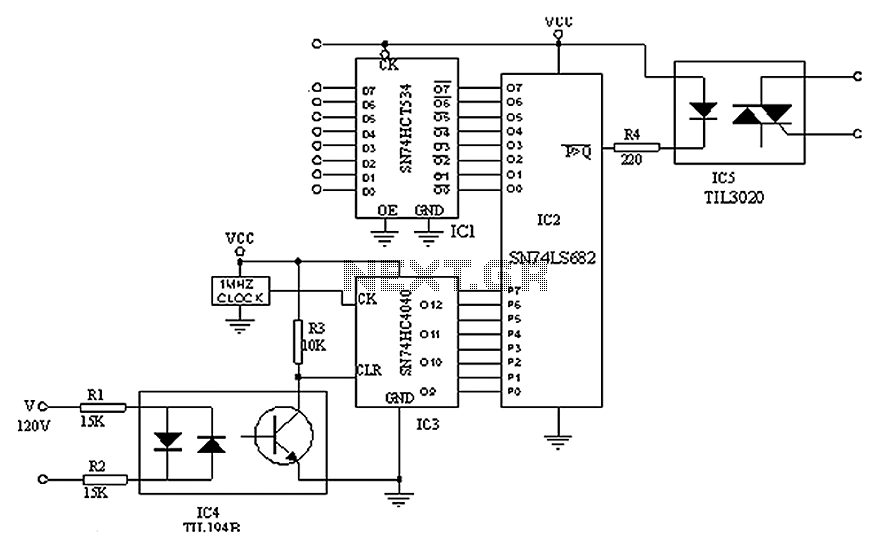
A simple digital circuit is presented that can be used to precisely control the AC power supply. This circuit does not include a digital-to-analog conversion component. In its application, effective control is established through a computer system that sends...
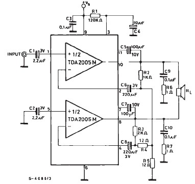
TDA2005 car audio amplifier circuit diagram electronic project using few external electronic parts The TDA2005 is a robust integrated circuit designed for audio amplification in automotive applications. This circuit diagram outlines a project for a car audio amplifier that utilizes...
This circuit is a five-channel equalizer designed for a single line channel. The working principle of this series involves a series of frequency filters with a center frequency of 10 Hz. The five-channel equalizer circuit is structured to manipulate audio...
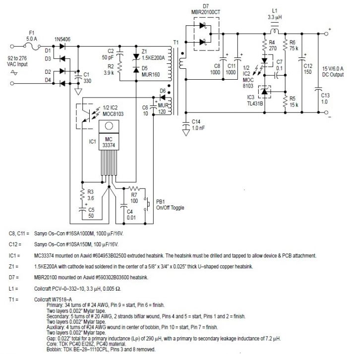
This switching power supply circuit diagram is based on the MC33374 high-power voltage switching regulator IC manufactured by Motorola Semiconductor. The MC33374 switching power supply circuit will provide a maximum output power of around 90 W and requires few...