
A8902 Typical application wiring diagram

The A8902 wiring diagram illustrates the connection and interaction between various components in a motor control system. This diagram includes essential elements such as the delay island, circuit breaker (CB) 11, the motor brake, and the motor itself.
In the event of a system failure, the delay island generates a failure signal which is sent to circuit breaker CB 11. This circuit breaker acts as a protective device, interrupting the power supply to the motor brake and halting the operation of the motor. The motor remains inoperative until a RESET signal is received, indicating that the fault has been addressed and the system can resume normal operations.
Upon receiving the RESET signal, the motor brake is released, allowing the motor to restart. This sequence ensures that the motor does not operate under potentially damaging conditions following a fault, thereby enhancing system reliability and safety.
The wiring diagram for the A8902 is crucial for troubleshooting and maintenance, as it provides a clear representation of how components are interconnected. Proper understanding of this diagram is essential for engineers and technicians working with motor control systems to ensure effective operation and maintenance procedures.A8902 ; A8902 is a typical application wiring diagram. After a system failure signal by the delay Island and CB 11 feet into the motor brake, stop stop work until the RESET sig nal arrives, the motor restarts.
Related Circuits
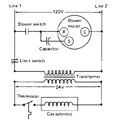
The gas furnace is the simplest to operate and understand. Therefore, it will be used here to examine a typical heating system. This type of natural gas furnace is utilized to heat millions of homes in the United States....
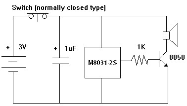
The M8031 circuit features an integrated RC oscillator and digital envelope circuits, which minimize the need for external components. It produces a sound that mimics a mechanical ding-dong. The M8031 operates with a low input voltage range of 1.3...
Renewable energy discussions encompass various alternative energy, renewable energy, and free energy technologies. Discussions about environmental issues, global warming, and other related topics are also welcome. It is important to address the validity, organization, and general advice concerning the...
The UC3842AN is a pulse width modulation (PWM) integrated circuit that is commonly utilized in DVD, VCD, and SVCD players, as well as in computers, display systems, and various household appliances' switching power supply circuits. The UC3842AN is a...
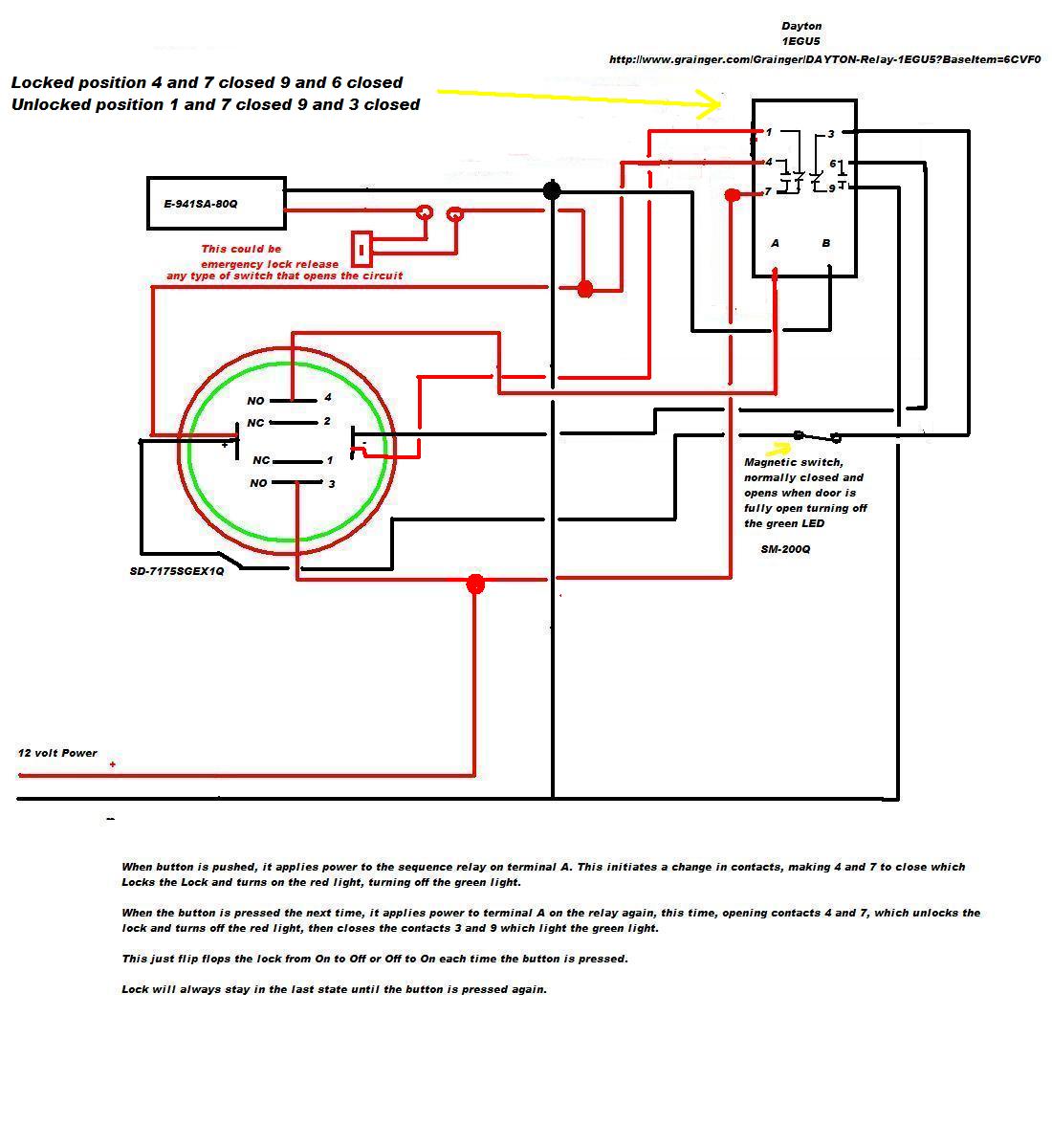
A 12V DC electromagnetic lock is designed with a push-to-lock and push-to-unlock mechanism using an existing LED indicator/switch. The switch should display a green light when unlocked and red when locked. The LED indicator/switch is the SD-7175SGEX1Q, which is...
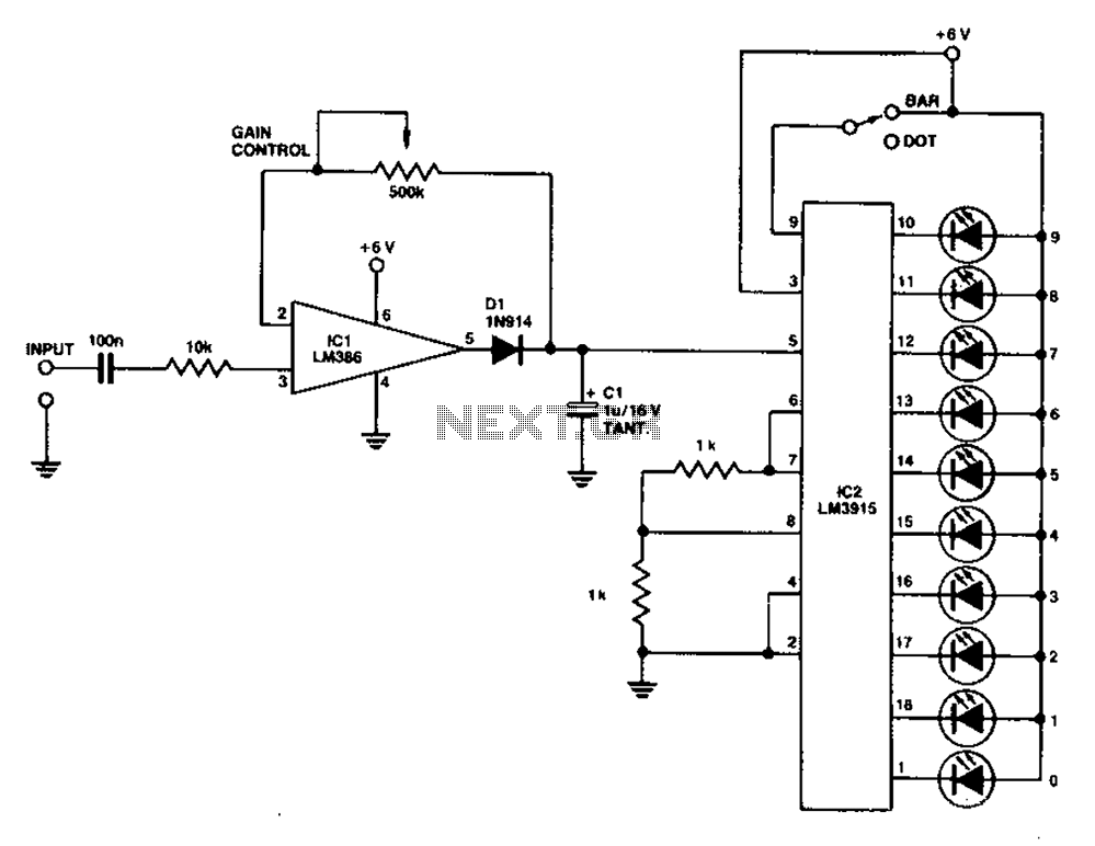
A simple level power meter designed to provide a high-fidelity sound system with a bar or dot matrix display. The green LED display indicates levels from 0 to 7; level 8 is shown in yellow, and level 9 is...