
GAS FURNACE OPERATION AND DIAGRAM

The gas furnace operates through a series of interconnected components that ensure efficient heating and safety. The primary elements include the gas solenoid, limit switch, blower switch, thermostat, and the transformer. The transformer is critical as it converts high voltage to low voltage, enabling control of the gas solenoid.
The limit switch serves as a safety feature; it opens to cut off power to the transformer if the furnace overheats, preventing potential hazards. The gas solenoid is responsible for controlling the flow of gas to the burner, which is ignited by the pilot light. When the thermostat detects a drop in room temperature, it closes, sending 24 volts to the gas solenoid, allowing gas to flow and ignite, thus heating the air in the plenum.
As the air temperature in the plenum rises to 120 degrees Fahrenheit, the fan switch activates, supplying 120 volts to the fan motor, which circulates warm air throughout the home. The cycle continues until the desired temperature is reached, at which point the thermostat opens, de-energizing the gas solenoid and shutting off the gas supply.
The blower continues to operate until the temperature in the plenum falls to 90 degrees Fahrenheit, at which point the blower switch opens, turning off the blower. This cyclical process ensures that the home maintains a comfortable temperature while prioritizing safety through the use of limit and blower switches. The gas furnace design exemplifies a straightforward yet effective heating solution widely adopted in residential settings.The gas furnace is the simplest to operate and understand. Therefore, we will use it here to look at a typicalheating system. This type of natural-gas furnace is used to heat millions of homes in the United States. Note the location of theblower switch and the limit switch. The transformer provides low voltage for control of the gas solenoid. Ifth e limit switch opens (it is shown in a closed position), there is no power to the transformer and the gas solenoidcannot energize. This is a safety precaution, because the limit switch will open if the furnace gets toohot. When the thermostat closes, it provides 24 volts to the gas solenoid, which energizes and turns on thegas.
The gas is ignited by the pilot light and provides heat to the plenum of the furnace. When the air in theplenum reaches 120 degrees F, the fan switch closes and the fan starts. The fan switch provides the necessary120 volts to the fan motor for it to operate. Once the room has heated up to the desired thermostat setting, the thermostat opens. When it opens, thegas solenoid is de-energized, and the spring action of the solenoid causes it to close off the gas supply, thereby turning off the source of heat. When the plenum on top of the furnace reaches 90 degrees F, the blower switch opens and turns off theblower.
As the room cools down, causing the thermostat to once again close, the cycle starts over again. Thegas solenoid opens to let in the gas, and the pilot light ignites it. The heat causes the temperature to rise inthe plenum above the limit switch`s setting, and the switch closes to start the blower. Once the thermostatsetting has been reached, it opens and causes the gas solenoid to turn off the gas supply.
The blower continuesto run until the temperature in the plenum reaches 90 degrees F, and it turns off the blower by opening. 🔗 External reference
Related Circuits
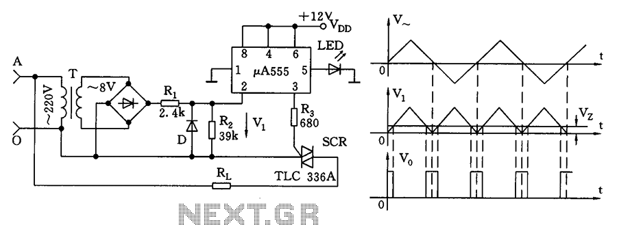
The zero volt switching circuit generates a trigger pulse at the zero crossing of the AC voltage. To facilitate this, the zero crossing of the 555 limit comparator is connected to a single form, with the comparison voltage set...
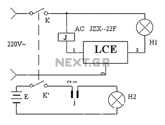
The application circuit operates the device as illustrated below, allowing for intermittent lighting in specific situations (e.g., during surgery). It utilizes an LCE module for blackout emergency lighting, which activates automatically after a power failure, ensuring uninterrupted illumination. In...
555 low power timing circuit diagram. The diagram is from the technical information of Chinaicmart. For more detailed information about the circuit diagram. The 555 timer IC is widely utilized in various applications due to its versatility and ease of...
Men often appreciate the convenience of television remote controls, which can sometimes frustrate their female partners. They tend to switch channels frequently, wanting to ensure they do not miss anything while a specific program is on. With the remote...
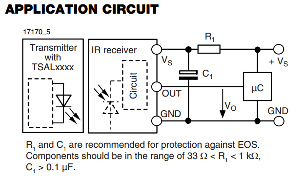
There is an interest in starting an introductory electronics project using an infrared (IR) sensor, but there is some confusion regarding the application circuit provided in the datasheet. The recommended resistor value is significantly lower than the calculated value....
The use of electrically excited gas discharges significantly predates the invention of the incandescent lamp. Physics laboratories, both historical and contemporary, utilize various gas-filled tubes for multiple applications, including light generation for spectroscopy, materials analysis, gas dynamics studies, and...