
I need a circuit diagram and parts list to install a 12v DC
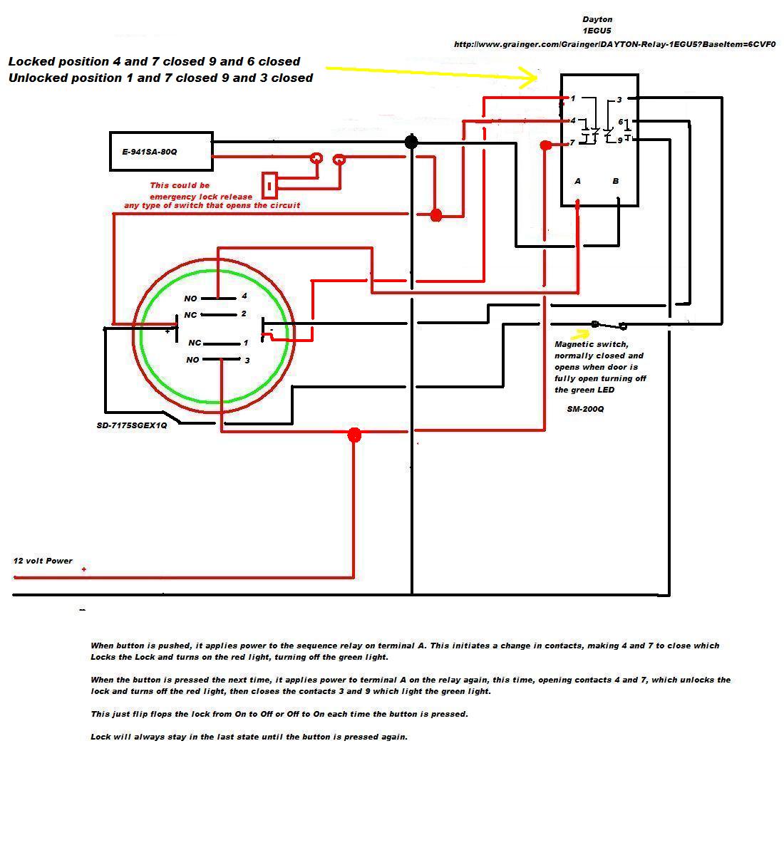
The circuit design incorporates a 12V DC electromagnetic lock controlled by a relay module, which is activated via a momentary contact switch (SD-7175SGEX1Q). This switch interrupts the circuit when pressed, allowing for a toggle between locked and unlocked states. The relay module (SR-1212-C2ALQ) is configured to switch the power to the lock based on the state of the LED indicator switch.
The LED indicator will change colors based on the lock state: green for unlocked and red for locked. This is achieved by connecting the LED's anode to the positive terminal of the power supply and the cathode to the relay output, which connects to the lock. The relay is configured to provide a path to ground when activated, allowing the LED to illuminate appropriately.
To enhance functionality, a leaf or magnetic switch is installed to detect the door's position. When the door is closed, this switch triggers the relay, energizing the lock circuit and turning the LED red. The mechanical switch allows for manual unlocking from the outside, providing an emergency release mechanism. This switch is wired in parallel with the relay, ensuring that it can interrupt the power to the lock even if the relay fails.
The design includes provisions for reliability, especially for the open position switch, which must be durable due to the nature of the application. The soft close/open mechanism of the doors provides adequate actuation force, ensuring that the switches operate effectively.
In summary, the circuit integrates an electromagnetic lock, a relay module, and a momentary contact switch with an LED indicator, alongside additional safety features for emergency access and reliable operation in a residential restroom setting. The design prioritizes both functionality and aesthetics, ensuring a seamless user experience while maintaining a high-end appearance.A 12v DC electromagnetic lock with push to lock and push to unlock using my existing LED indicator/switch. The switch should indicate green when unlocked and red when locked. The LED indicator/switch is SD-7175SGEX1Q from It is momentary contact and is intended to be used as a "push and hold to exit" switch which interrupts the circuit while it is being pressed, but I would very much like to use it as
it is esthetically perfect for my application. It is 12v DC and has 3 pairs of pins: I also have a SR-1212-C2ALQ High Sensitivity Relay Module, also from and also 12v DC. It is 2 amp DPDT with trigger inputs. If additional relays are needed, I would prefer to use relays from Seco-Larm, since I have had good ordering experience with them, but am open to other sources.
I would like to optionally include a mechanical switch to energize the circuit in locked position when the door is closed. Once closed, however, the LED indicator switch should still be able to unlock and lock. Is it at all possible to use 2 switches, one for lock and one for unlock if the wiring will not allow the use of one switch (unsure till a schematic is made) optionally include a mechanical switch to energize the circuit in locked position when the door is closed.
Once closed, however, the LED indicator switch should still be able to unlock and lock. Sorry to take so long to reply (I also work for a living). This is for the restrooms in a high-end home. The doors are pocket doors with a soft close and soft open mechanism. The idea is that the doors are normally open. When someone goes into the restroom and slides the door shut, it closes slowly and a leaf or magnetic switch will cause a relay to energize the circuit to closed and turn the led red. When the person is ready to open the door, they push the button and it turns green and kills the power to the lock.
If they change their mind, they push the button again and it turns red and powers the lock. The pushbutton is very attractive silver metal with an led ring surrounding it, so having two buttons wouldn`t look right. I understand it may be problematic to change the polarity of the switch 12v input each time it is pushed, but if it can be done, that`s what I want.
If you have an email address, I can send you the schematics that came with everything, but I know we`re using them in a somewhat different manner than they were designed for. About the second switch, to make it work the way I would most prefer, may take two switches, one to detect completely open, and one to detect completely closed: The completely open switch needs to be high reliability as it would be painful to replace.
The soft open/soft close mechanism provides sufficient pulling/pushing force to work most switches. Emergency Lock Release (added to the diagram, could be any type of switch you choose to open the power to the lock directly in an emergency on Pushbutton or relay failure. ) So, you can think on that part as I try to work around that switch and somehow get power removed and stay removed until the door is opened away from the switch.
I was going to mount a momentary contact kill switch on top of the outside door jamb to open the door if someone closes it from the outside, but I`m ok with eliminating the auto-lock and the fully closed switch. So it will work like this: We only use one magnetic switch to sense the fully open position. We use one mechanical switch to interrupt the circuit and unlock the door from the outside in case some little kid gets stuck inside.
I just finished wiring it up. We`re getting close. The relay is powering the lock on and off each time the switch is depressed with the relay doing it`s job. However the light is inoperative. Here`s what I found: 1. If I measure from the positive terminal on the led switch to the negative terminal on the power transformer I get 12 volts (when the lock is ene
🔗 External reference
Related Circuits
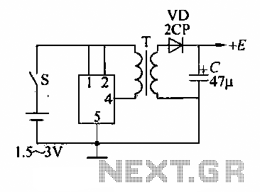
A DC booster circuit is illustrated in the figure, which represents a step-up transformer circuit diagram. The step-up transformer (T) can be utilized to power small transistor radios. The winding ratio can be adjusted to achieve the desired output...
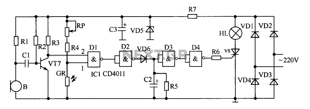
The delay-saving lamp circuit functions as a sound and light control delay energy-saving lighting system. It can directly replace a standard light switch without modifying the existing lighting circuits. In bright or daytime conditions, the sound control feature ensures...
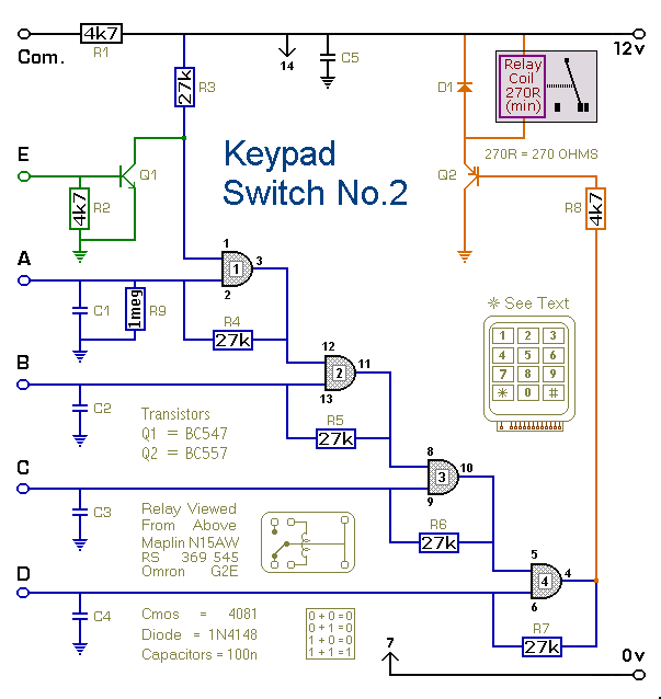
This is a simplified version of the 4-Digit Keypad Controlled Switch. The design has been modified to reduce the complexity of the circuit and the number of components required. Consequently, the code may be somewhat less secure; however, it...
This audio limiter circuit is simple to construct and is compatible with BA741 operational amplifiers, whether in 8-pin or 4-pin configurations. It requires a symmetrical power supply. The circuit is designed to manage audio input levels effectively. The audio limiter...
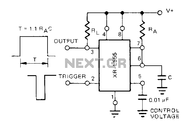
The Exars XR-L555 circuit has a typical power consumption of 900 W and operates with a power supply voltage of 5V. It is a micro-power circuit that can be used as a direct replacement for the standard 555 timer....
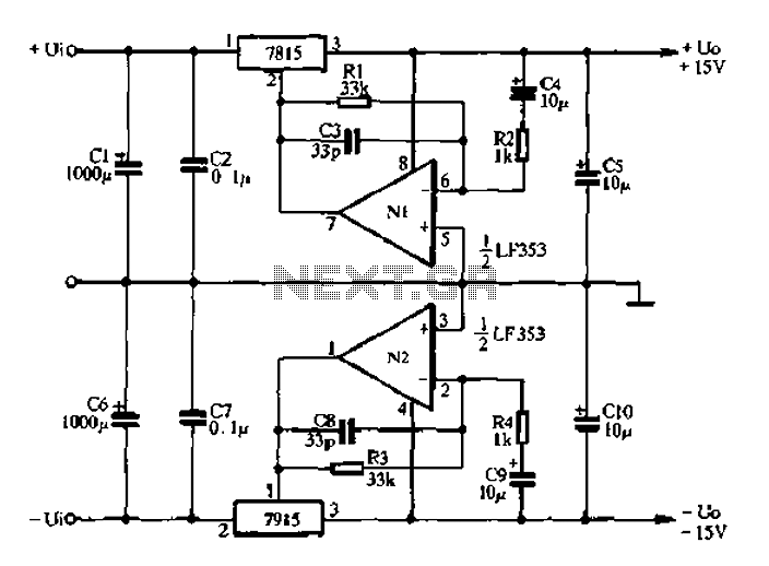
15V active servo power supply circuit The 15V active servo power supply circuit is designed to provide a stable and regulated output voltage of 15 volts, suitable for powering servo motors and other related devices. This circuit typically employs a...