
Kapagen Winding Diagrams

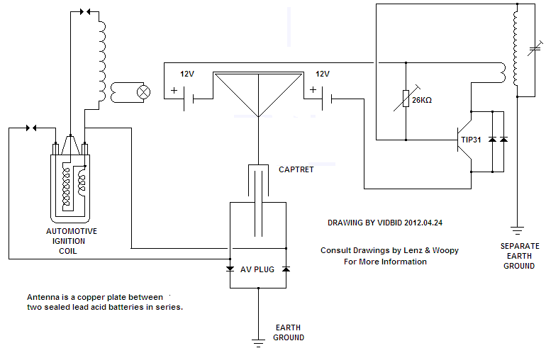
The schematic indicates that the device requires an initial input of energy, which passes through a transformer, diode, capacitor, and spark gap setup before reaching the custom coil, the only original part of the device. Common misconceptions arise when individuals attempt to replicate Tesla's ground current theories without fully understanding the design. For effective operation, builders must recognize that achieving a current flow in the soil requires a potential difference; the water and metal radiator act as excellent electron transfer mediums. This step is crucial for the Kapagen device's functionality, yet it is frequently overlooked.
The device is designed to start with a load, after which the input source can be removed, allowing the ground connections to take effect. The potential difference varies continuously, maintaining current flow through the coil. It is a misconception that the load cannot be supplied without continuous input energy; the coil is designed to maintain equilibrium and draw from the ground as needed. If only two metal poles are grounded, the potential difference will not accommodate the variable electron demand, leading to failure of the magnetic field.
The Kapagen device is not solely responsible for the technology discussed; it shares principles with other free energy devices like Kapanadze, Mace-Meyer, and Hendershot. The core of these devices, whether a winding or another conductor, is essential. The phenomena of capacitance, which involves electrical energy storage in a field, can be related to the oscillating coil. The understanding of capacitance must be broadened beyond traditional definitions.
The interaction of magnetic fields and the timing of operations are critical for the successful functioning of these devices. The Kapagen device can be seen as a composite coil assembly that acts as an alternating or pulsed NMR inducing resonator. The design must ensure that circuit operations do not coincide to allow for the sequential induction of emanations and their transduction.
In summary, the Kapagen device and similar technologies rely on understanding the fundamental principles of electromagnetism, timing, and the interaction of magnetic fields. The design and implementation of these devices require careful consideration of the components and their arrangement to achieve desired outcomes.Renewable Energy Discussion on various alternative energy, renewable energy, & free energy technologies. Also any discussion about the environment, global warming, and other related topics are welcome here.
I will just mention a few things in here which address a validity, organization, and general advice concerning the kapagen device. General: on e of the main reasons you cannot find alot of people, amongst the long list of people who have built one of these, is due to the fact they wish to build the device, perhaps you could say "as is", and should be building a much small scaled down version which would be much easier to test and evaluate, as well as much cheaper. The second general reason is because people too often like to read schematics of details and pick and choose what they think makes the most sense, and what does not, and this error prevents them from every really building a working prototype, or simply claiming it does not work.
Validation and location of the parts you have missed, as referred to above: the kapagen device is not complicated at all, and relies completely on known and understood physics. If any of you have mentioned this device to someone with a Ph. D. perhaps at a school you have found that they claim it violates laws and therefore is wrong, but they are simply choosing not to acknowledge anything new, as they have no answers as to why it works.
This is how it works: the schematic indicates it must have an input of energy to get it started, and this runs through a run of the mill transformer/diode/capacitor/sparkgap setup, and then into the only part of the device which is somewhat original the custom coil. I am not going to go any further because this is the single location of all failures. People read things about Tesla`s ground current and think well I stick one metal rod here and one here and why am I not getting what was promised, and the answer is because you must read into the design.
Similarly, people put everything together and put two poles in ground and turn it on and get ~96% return if they are diligent in design, however most get less. Well it should occur to the builder (I forgot the water bank which was buried in the ground). Getting a current to flow in the soil from one point to another still requires a potential difference people, and the water (excellent e- transfer medium) combined with the metal radiator (excellent e- transfer medium) will be able to get the available e-`s out of the soil.
This step is the only reason the actual kapagen device works, and is nearly always flawed or left out entirely. The common misconception, even on the jlnaudin site, is that the kapagen is designed to receive a continual input, and this is wrong.
The device is designed to be started, with some load, and once running the input source is removed, and the ever important ground connections are put into action. It is designed in such a way that the potential difference will vary continuously, and it is in this difference the device will attempt t maintain the flow of current through the coil.
Now an additional misconception, well how would my load get supplied without input energy won`t it drop once I unplug the input No, the coil was designed and is used with the understanding that it will try to maintain its equilibrium. This requires it pull from the ground more or less depending on the load, and the load only pulls from the magnetic field inside the coil.
By pulling from the magnetic field the field will be disrupted and the coil will seek to reestablish equilibrium, and begin to pull from the only input remaining the two ground connections. If you have just to metal poles in ground at this point the potential difference will not allow for expansion and contraction of the variable need for e-`s and the magnetic field will fail.
when you look at it this way you might say why have I not thought of this complexity sooner, and the answer is it is natural to try and reduce complexity, and if done enough it can be subconscious. I have only seen one video to date where the device was connected correctly and worked as described above.
For anyone building this device I highly recommend following the original kapagen schematic and not jlnaudin as it is wrong, and only try for an output which standard non-specialized meter equipment can handle to measure. For those of you still reading you should be looking into device combinations, as each device has a weak spot, due to the fact the researcher was devoted to proving their idea correct, and failing to notice that they could have accomplished some components operations in an easier manner.
I am currently working on a few hybrids and will be posting things to the internet for confirmation of what has been discussed here. Yet this is NOT Kapagen only technology, and to think it so will merely close minds as to the reality of what *ALL* other free energy devices like Kapanadze, Mace-Meyer, Hendershot and the earliest I know of - Hubbard have been doing.
Something I must agree with - is the Tesla like `spark techniques`, as so endlessly tried with Don Smith circuitries, are not essential to the running of these devices, but a core is, even if that core is coincidentally a winding or some apparently essential longitudinal conductor ! Now before I go any further I wish to state that I am not a `scientist`, though I have managed to gain a reasonable understanding of the fundamental principles which the `qualified experts` so cleverly package such that we might never come to learn of or accept as actually being possible, for indeed the "experts" write texts and educationally examine us to check that we follow and repeat their dogmas, so that we might never comprehend what is really going on with ALL of these generators.
In other words, they are willfully concealing the Truth ! Dave, you for one are making so much effort here in trying to share an understanding, and so I am thankful that my first visit here coincidentally sees me opening up the highlighted `explanation` you found, for without that I would have just gone away again. By pulling from the magnetic field the field will be disrupted and the coil will seek to reestablish equilibrium, and begin to pull from the only input remaining the two ground connections.
If you have just to metal poles in ground at this point the potential difference will not allow for expansion and contraction of the variable need for e-`s and the magnetic field will fail. The ground does not/ cannot supply electric current as an input to the Kapagen coil assembly, and thus this explanation is clearly, if unintentionally, incorrect.
It is only when we look at these *composite* coil assemblies as alternating or pulsed NMR inducing resonators, plus NMR transducers, that what is occuring within all of these devices can be understood ! Look at the windings in the videos - reversed fields between ends generating same polarity magnetic field impingement upon molecular domains within some central region of the core.
The opposing winding fields and interacting core current induce electron *orbit* spins within the core molecular domains, thereby not only exciting the electrons, but disrupting their fundamental orbital relationship with the elemental nucleus; ie. - abnormally dissociating electron motion about two axes, through generating force against along the third axis within a three dimensional molecular substance).
There cannot be change to, or energetic loss of, the electrons of any atom within a body which is sharing electron bonds, without there being equal but opposite reaction upon and within associated nucleii = EM induced artificial radioactive decay + transducible energy release. This decay causes both voltage charge to the core (core earthed on the Kapagen thus creating fractionally time delayed transducible output through cable-Earth reflection) plus radioactive emanations which additionally become transduced by surrounding metal overwindings, and induce displaced electron motion with transducible energy output.
In the Hendershot generator the time delay comes from emanations being transduced by a core-cap foil overwind, this reactively (delay) parallel energising another separate coil winding. The most important aspect with all of these devices relates to timing, for the induction of emanation and its subsequent transduction arise sequentially, and thus must not be coincidentally damped by failure to ensure non-simultaneous circuit operations before both effects can manifest.
Also do be aware that the `experts` provide us with fantastic high NMR frequency reference listings, applicable to a high strength polarising magnetic field quite unlike that on the Earthly environment we occupy - a `scientific` fantasy, which is deliberately neither relevent to everday circuitry at low magnetic (earth) field strengths, nor usable by the masses ! Within our Earthly environment NMR excitations commonly arise at hundreds and kilohertz frequencies, and thus I wonder if Fleischman and Pons, and Stan Meyer energised their water based technologies at clearly audible frequencies too Heck look at the NMR T1/ T2 time periods used with MRI equipment; the scans might run at MHz, but the molecular re-alignments take hundreds of microseconds unless moving, as in blood, and hence the scan field repetition pulses are so slow we can count them !
Two separate earthing wires will present necessary time delay for many Kapanadze version generators, but so too would a twin conductor delay line between two cross interconnected coils with adjustable mutual coupling, as Hendershot did with his NMR corecap assemblies and mechanically resonant (pulse time delaying) `buzzer` assemblies ! Thus the Kapagen has been cleverly fashioned such that it is the transduced loading of emenating core energy which closed loop (though with reactive delay) induceses NMR excitation, thus increased loading automatically increases excitation of electrical output.
It would seem in a solenoid configuration that current would travel through the core to some extent but a toroid should exclude the electric field completely. It would seem in a solenoid configuration that current would travel through the core to some extent but a toroid should exclude the electric field completely.
Something I must agree with - is the Tesla like `spark techniques`, as so endlessly tried with Don Smith circuitries, are not essential to the running of these devices, but a core is, even if that core is coincidentally a winding or some apparently essential longitudinal conductor ! The phenomena of capacitance is a type of electrical energy storage in the form of a field in an enclosed space.
This space is typically bounded by two parallel metallic plates or two metallic foils on an intervening insulator or dielectric. A nearly infinite variety of more complex structures can exhibit capacity, as long as a difference in electric potential exists between various areas of the structure.
The oscillating coil represents one possibility as to a capacitor of more complex form, and will be presented here. The perception of capacitance as used today is wholly inadequate for the proper understanding of this effect.
Steinmetz mentions this in his introductory book Electric Discharges, Waves and Impulses. To quote, "Unfortunately, to large extent in dealing with dielectric fields the prehistoric conception of the electrostatic charge (electron) on the conductor still exists, and by its use destroys the analogy between the two components of the electric field, the magnetic and the dielectric, and makes the consideration of dielectric fields unnecessarily complicated. " Steinmetz continues, "There is obviously no more sense in thinking of the capacity current as current which charges the conductor with a quantity of electricity, than there is of speaking of the inductance voltage as charging the conductor with a quantity of magnetism.
But the latter conception, together with the notion of a quantity of magnetism, etc. , has vanished since Faraday`s representation of the magnetic field by lines of force. " All the lines of magnetic force are closed upon themselves, all dielectric lines of force terminate on conductors, but may form closed loops in electromagnetic radiation. These represent the basic laws of lines of force. It can be seen from these laws that any line of force cannot just end in space. Farady felt strongly that action at a distance is not possible thru empty space, or in other words, "matter cannot act where it is not.
" He considered space pervaded with lines of force. Almost everyone is familiar with the patterns formed by iron filings around a magnet. These filings act as numerous tiny compasses and orientate themselves along the lines of force existing around the poles of the magnet. Experiment has indicated that a magnetic field does possess a fibrous construct. By passing a coil of wire thru a strong magnetic field and listening to the coil output in headphones, the experimenter will notice a scraping noise.
J. J. Thompson performed further experiments involving the ionization of gases that indicate the field is not continuous but fibrous (electricity and matter, 1906). Consider the space between poles of a magnet or capacitor as full of lines of electric force. See Fig. 1. These lines of force act as a quantity of stretched and mutually repellent springs. Anyone who has pushed together the like poles of two magnets has felt this springy mass. Observe Fig. 2. Notice the lines of force are more dense along AB in between poles, and that more lines on A are facing B than are projecting outwards to infinity.
Consider the effect of the lines of force on A. These lines are in a state of tension and pull on A. Because more re pulling on A towards B than those pulling on A away from B, we have the phenomena of physical attraction. Now observe Fig. 3. Notice now that the poles are like rather than unlike, more or all lines pull A away from B; the phenomena of physical repulsion.
The line of force can be more clearly understood by representing it as a tube of force or a long thin cylinder. Maxwell presented the idea the tension of a tube of force is representative of electric force (volts/inch), and in addition to this tension, there is a medium through which these tubes pass.
There exists a hydrostatic pressure against this media or ether. The value of this pressure is one half the product of dielectric and magnetic density. Then there is a pressure at right angles to an electric tube of force. If through the growth of a field the tubes of force spread sideways or in width, the broadside drag through the medium represents the magnetic reaction to growth in intensity of an electric current. However, if a tube of force is caused to move endwise, it will glide through the medium with little or no drag as little surface is offered.
This possibly explains why no magnetic field is associated with certain experiments performed by Tesla involving the movement of energy with no accompanying magnetic field can be thought of as working in series. 🔗 External reference
Related Circuits
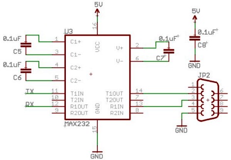
Select a free schematic drawing software that resembles the two mentioned. There have been discussions regarding circuit drawing software. Fritzing is favored, although it lacks certain components, such as the RS232 component. There is a request for feedback on...
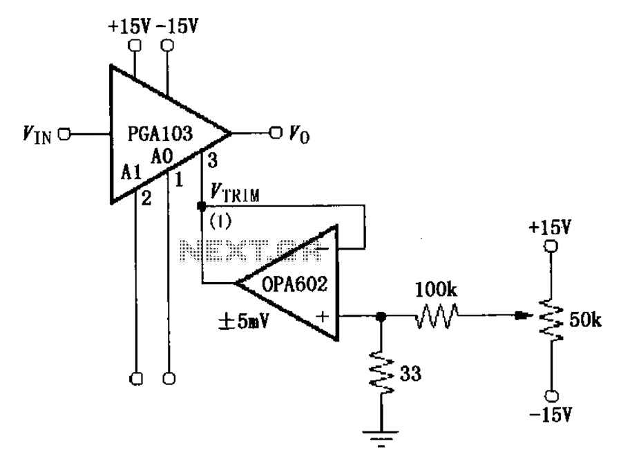
The PGA103 offset voltage correction circuit is designed to minimize the offset voltage for the PGA103 laser correction, ensuring that the gain for three typical offset voltage levels (relative to input) remains below 200 V. Each gain is associated...
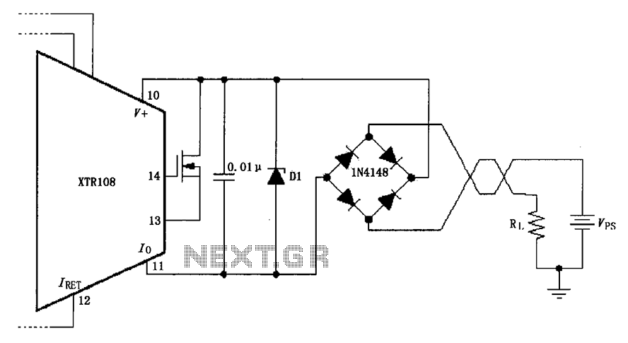
The circuit utilizes a Zener diode (D1) for overvoltage protection and a diode rectifier bridge for reverse voltage protection. The 1.4V drop across the diodes will result in a maximum voltage loss, meaning that the supply voltage (VPS) must...
This section describes the components of the receiver, which includes the post-mixer amplifier, variable crystal filter, intermediate frequency (IF) amplifier, product detector, local oscillator, receiver muting, and audio amplifier. The transmit section features the local oscillator, transmit single balanced...
Thank you for the diagram, Zinc. It looks very interesting. Please keep us informed of any results. I am MrFlathunter on YouTube, and you commented on my 12V. The circuit in question likely pertains to a 12V system, which is...
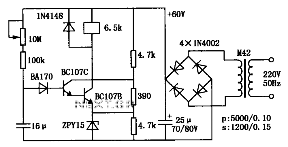
The circuit is a relay delay pull transistor configuration. Initially, when powered, the 16 µF capacitor has a voltage of zero, resulting in both transistors being off, and the relay remains inactive. As the 16 µF capacitor charges over...