
About a PWM power inverter
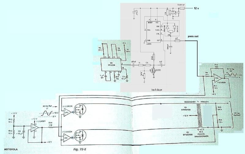
The 555 timer IC is widely used in various applications, including PWM (Pulse Width Modulation) generation. In constructing a PWM inverter using a 555 timer, the circuit can be simplified to avoid the complexities associated with microcontroller programming.
To create a basic PWM inverter circuit, the 555 timer is configured in astable mode, allowing it to generate a continuous square wave output. The frequency and duty cycle of the PWM signal can be adjusted by varying the resistors and capacitors connected to the timer.
The output of the 555 timer can drive a transistor or a MOSFET, which acts as a switch to control the power supplied to the load. The inverter circuit can then convert a DC input voltage into an AC output voltage, suitable for powering various devices.
Additional components such as diodes for flyback protection, capacitors for filtering, and inductors may be included to improve the performance and stability of the inverter. Proper heat dissipation measures should also be considered when selecting the switching components to ensure reliability during operation.
This approach to building a PWM inverter using a 555 timer provides a straightforward solution for those seeking to implement an inverter without the need for programming or complex circuitry.Hello I was, since few months, looking for an easy to build PWM inverter, and without any PIC programing. Looking at a 555 PWM amp circuit, I have an.. 🔗 External reference
Related Circuits
Amplifier with IC number TDA7293 for processing sound systems. This amplifier includes inputs for a radio, TV, stereo, or other line-level devices. It also features a phono input for a record player, guitar, microphone, or other unamplified sources. With...
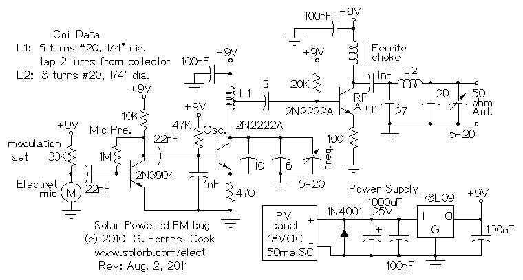
Here are some utility circuits for use with the Ramsey FM10a, and other small FM stereo transmitter kits. This information may be helpful for setting up a micro powered FM radio station. The FM10a and similar kits tend to...
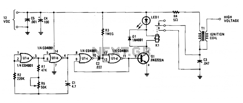
The circuit is fundamentally an auto ignition coil paired with a set of points that perform a similar function. It employs a pulsing circuit constructed from a single CMOS NOR integrated circuit (U1) to open and close relay contacts,...
PWM is a device that can be utilized as an efficient light dimmer or DC motor speed controller. Function: for a general-purpose device that can... PWM (Pulse Width Modulation) is a versatile technique widely employed in various electronic applications, particularly...
It is possible to easily generate various non-linear functions such as X^(1/2), X^2, X^3, 1/X, XY, and X/Y using logarithms. In this context, division is transformed into subtraction, while multiplication is converted into addition. The application of logarithmic properties in...
This is a power audio amplifier circuit based on the STK400xx series. It provides high-quality sound and is cost-effective, as the STK40xx series is affordably priced. The circuit can be easily constructed using only a few external components. The...
Warning: include(partials/cookie-banner.php): Failed to open stream: Permission denied in /var/www/html/nextgr/view-circuit.php on line 713
Warning: include(): Failed opening 'partials/cookie-banner.php' for inclusion (include_path='.:/usr/share/php') in /var/www/html/nextgr/view-circuit.php on line 713