
Battery-powered fence charger
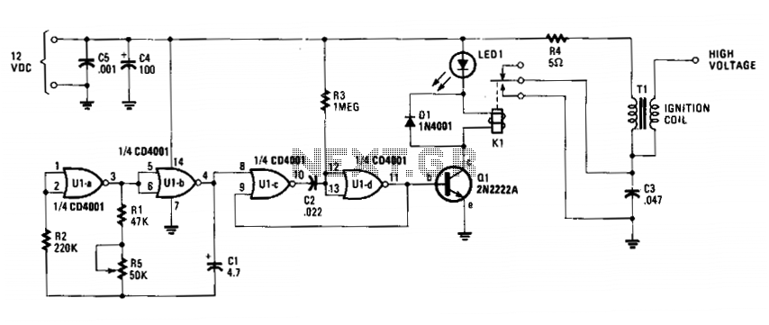
The circuit utilizes a CMOS NOR gate integrated circuit (IC), which is known for its low power consumption and high noise immunity. The configuration of the NOR gates in a feedback loop creates a stable oscillation, producing a square wave output. This output is essential for controlling the relay, which in turn activates the ignition coil. The relay acts as a switch that modulates the current flowing to the ignition coil, enabling the ignition system to function without the need for mechanical breaker points.
The timing components, including capacitor C1 and resistor R1, along with the variable resistor R5, are critical in determining the frequency of the oscillation. The capacitor charges and discharges through the resistors, creating a time delay that establishes the period of the square wave output. By adjusting R5, the frequency can be fine-tuned, allowing for optimal performance of the ignition system under varying conditions.
In summary, this circuit design effectively replicates the functionality of traditional ignition systems while providing enhanced reliability and efficiency through the use of solid-state components. The integration of a CMOS NOR gate offers advantages such as reduced power consumption and increased durability compared to mechanical systems. This makes the circuit suitable for modern automotive applications where electronic ignition systems are preferred.In essence, the circuit is nothing more than an auto ignition coil and a set of points which accomplishes the same thing. A pulsing circuit made from a single CMOS NOR integrated circuit (Ul), opens and closes the relay contacts to simulate the action of the original breaker points.
The relay pulser is divided into two clocking functions. The first circuit is a free-running squarewave generator that determines the rate or frequency of the pulses that activate the relay. It is essentially a pair of NOR gates connected as inverters and placed in a feedback loop, they are Ul-b.
The oscillating period of the feedback loop is determined by timing components CI, Rl, and variable resistor R5. 🔗 External reference
Related Circuits
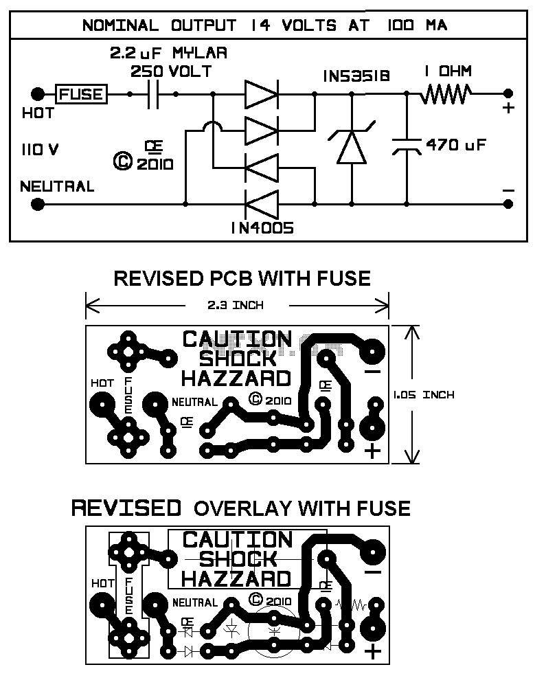
This circuit will not function unless the battery to be charged is connected with the correct polarity. The voltage of the battery regulates the charger, and when the battery is fully charged, the charger will stop supplying current to...
Bidirectional control is implemented for a motor to increase its operational degree. The motor can rotate in either direction with a current of 1A. A variable duty cycle multivibrator is utilized to achieve the construction and control of the...
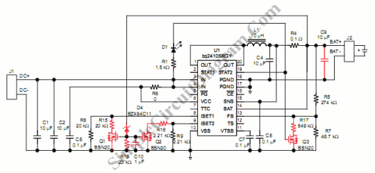
Switch mode circuits can implement a lead acid battery charger more efficiently. It can be constructed using the bq24105 battery charger controller. The bq24105 was originally designed to charge single, two, or three-cell Li-polymer and Li-ion battery packs. However,...
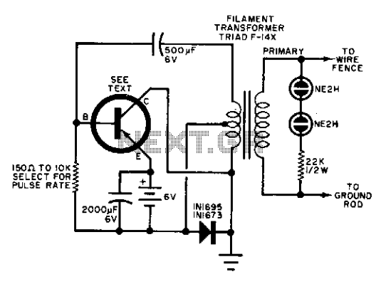
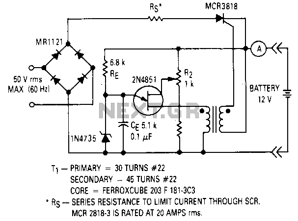
Any suitable power transistor can be utilized in this circuit. The base resistor must be calibrated to achieve a pulse rate of approximately 50 pulses per minute, with a possible range from 10 to 100 pulses per minute. The...

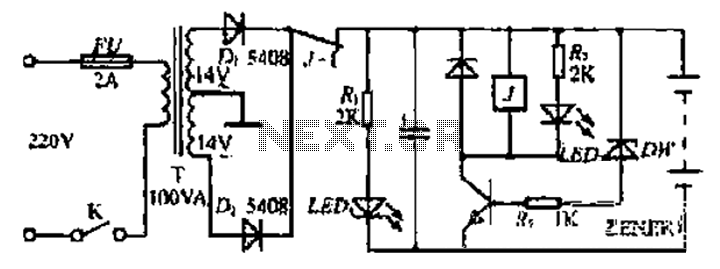
A simple battery charger circuit with reverse polarity indication is presented. The circuit utilizes the L200 integrated circuit, which is a five-pin variable voltage regulator. It can be powered by DC voltage from either a bridge rectifier or a...
Using this circuit will give good charging results to a sealed lead acid battery, like I use in the metal detector. This circuit is extremely small in size and has a low parts count, making it ideal in some...
Warning: include(partials/cookie-banner.php): Failed to open stream: Permission denied in /var/www/html/nextgr/view-circuit.php on line 713
Warning: include(): Failed opening 'partials/cookie-banner.php' for inclusion (include_path='.:/usr/share/php') in /var/www/html/nextgr/view-circuit.php on line 713