
Micro Power FM Broadcasting Circuits

The Ramsey FM10a and similar FM stereo transmitter kits are designed for low-power FM broadcasting, typically operating in the 88-108 MHz band. These circuits are essential for hobbyists looking to set up micro-powered FM radio stations. The FM10a is known for its simplicity and ease of use, but it often produces a broad bandwidth output signal that may not meet higher quality audio standards.
To enhance the performance of these transmitters, utility circuits can be integrated. These may include low-pass filters to improve signal quality by attenuating unwanted harmonics and noise, thus ensuring that the transmitted signal remains within the designated frequency band. Additionally, impedance matching circuits can be employed to optimize power transfer between the transmitter and the antenna, helping to maximize the effective radiated power without exceeding legal limits.
When considering amplification, it is crucial to remain within the 5-10 milliwatt output range. Amplifying beyond 50 milliwatts can lead to interference with other licensed radio services, which may attract regulatory scrutiny. Therefore, any amplification stage should be carefully designed to ensure compliance with local regulations while enhancing the audio fidelity of the transmission.
In conclusion, while the Ramsey FM10a and similar kits provide a foundation for micro-powered FM broadcasting, incorporating utility circuits such as filters and impedance matching can significantly improve performance. Careful consideration of power levels is essential to maintain compliance with broadcasting regulations and avoid interference with other radio services.Here are some utility circuits for use with the Ramsey FM10a, and other small FM stereo transmitter kits. This information may be helpful for setting up a micro powered FM radio station. The FM10a and similar kits tend to put out a low quality, broad band output signal. This is not a big problem with a 5-10 milliwatt signal, but amplifying the output of such kits beyond 50mw is a bad idea, as the amplified signal can cause interference with other radio services, drawing unwanted attention to your hobby station.
🔗 External reference
Related Circuits
A 6V to 12V DC converter circuit is designed to convert a lower voltage of approximately 6 volts to a higher voltage of 12 volts, albeit with a reduced current rating. This inverter circuit can deliver up to 800mA...
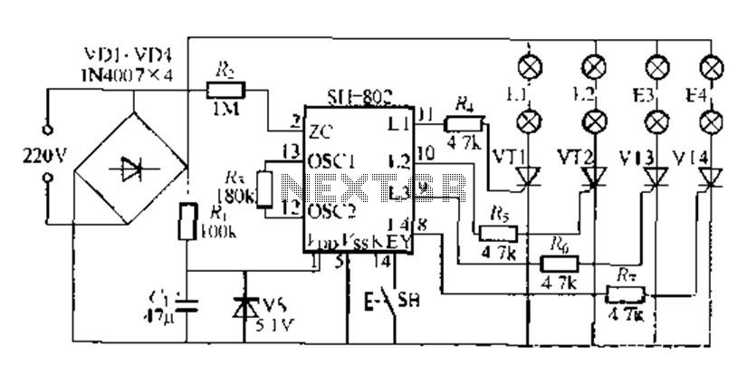
A digital integrated circuit simplifies the response process significantly. The diagram illustrates a circuit comprising four responder groups. The digital integrated circuit described serves as a crucial component in various electronic systems, primarily focusing on enhancing response efficiency. It comprises...
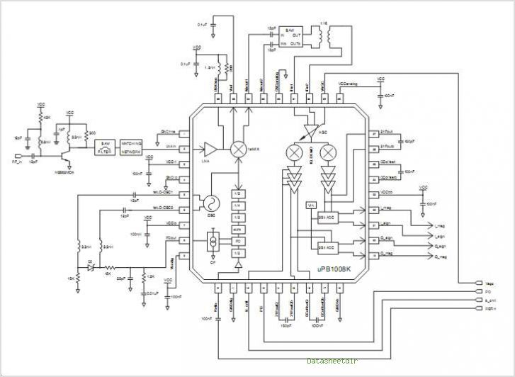
The PB1009K is a silicon monolithic integrated circuit (IC) designed for GPS receivers. This IC incorporates a complete voltage-controlled oscillator (VCO), a second intermediate frequency (IF) filter, a 4-bit analog-to-digital converter (ADC), and a digital control interface, all aimed...
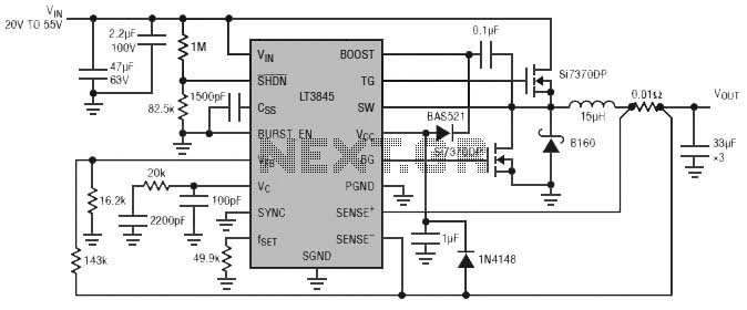
Burst Mode operation maintains high efficiency at light loads by reducing IC quiescent current to 120 µA. Light load efficiency is also improved with the reverse inductor current inhibit function, which supports discontinuous operation. Additional features include an adjustable...
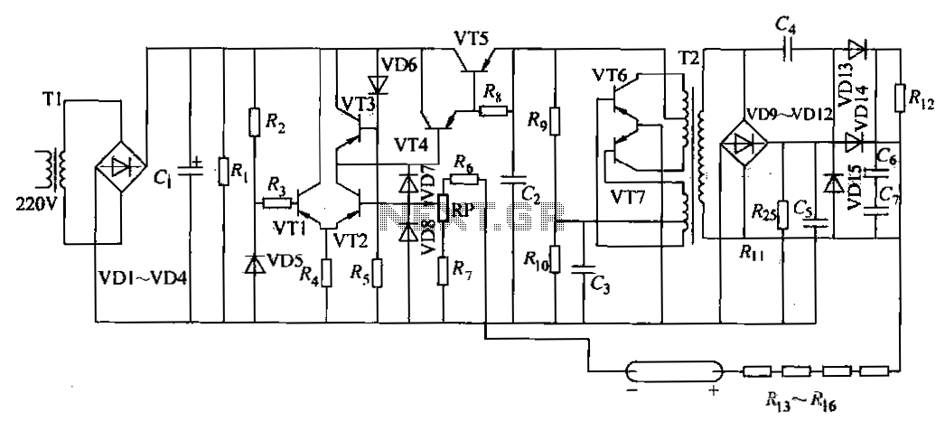
The DC power supply is a helium-neon laser excitation power supply, which is currently the most commonly used type of power supply. It is utilized in laser printers. The circuit includes a power transformer (T1), a high-voltage transformer (T2),...
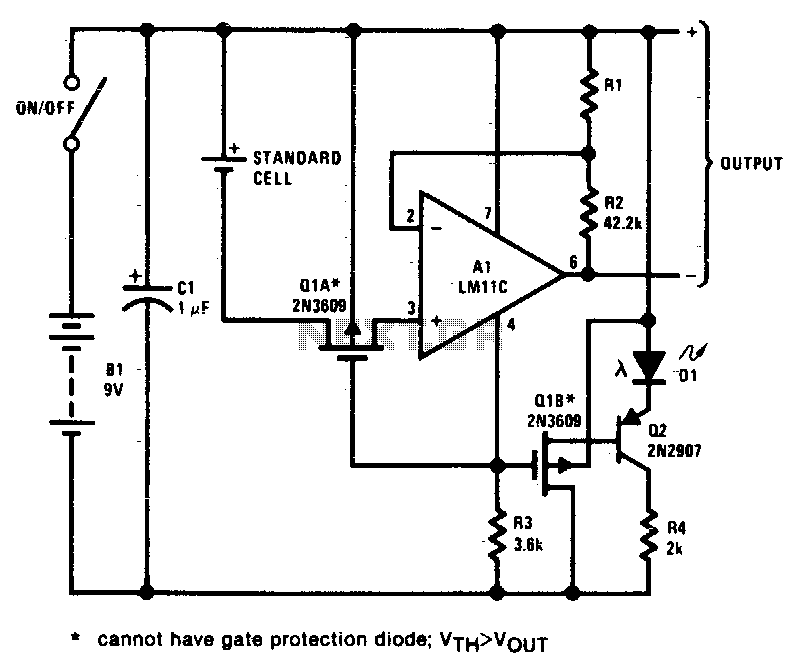
This circuit exhibits negligible loading and disconnects the cell in response to low supply voltage or an overload on the output. Additionally, the indicator diode turns off when the disconnect circuitry is activated. The circuit design incorporates a voltage monitoring...