
AC Arduino dimming circuit

The circuit operates by controlling the power delivered to a load, such as a lamp or fan, through pulse-width modulation (PWM) facilitated by the Arduino. The IRF730 serves as a switching element, capable of handling high voltages and currents without overheating. The bridge rectifier converts the AC input to DC, allowing the Arduino to control the transistor effectively. The infrared detector receives signals from the SONY universal remote, enabling user-friendly dimming control from a distance.
To assemble the circuit, the ungrounded cord must be cut and stripped to expose a sufficient length of copper wire for secure connections. These wires should be connected to the perf board or screw terminals, which provide a stable platform for the components. The Arduino is programmed to interpret the signals from the infrared detector, adjusting the duty cycle of the PWM signal sent to the IRF730, thereby controlling the brightness of the connected load.
Safety precautions should be observed when working with AC voltages, including ensuring all connections are secure and insulated to prevent accidental contact. The use of a heat sink with the IRF730 is advisable to further dissipate heat and prolong the lifespan of the transistor. Overall, this circuit presents a practical solution for dimming low-voltage AC devices, leveraging readily available components and a straightforward control mechanism.I am not an engineer, just an experimenter and hacker and prototyper etc, so, thanks to people who know a lot more than I do, I learned that this is not safe to use NOTE: This can only be used to dim a unit that runs off of a transformer-based power supply, ie something that doesn`t run off of 120 V, but 12, 24, or 48 Volts. Solder iron, wire stri ppers, breadboard or perf board, wires, 9V battery, IRF730 transistor, bridge rectifier, Arduino, infrared detector ( like this one ), SONY universal remote control ( like this one ) ButI had been trying for a number of weeks to perfect this, as in, find the correct transistor that would not overheat or burn out (one that is rated for a high enough voltage since it`s using AC 120 V). I followed this circuit from Dmitri`s blog, except instead of the IRF 250 I used an IRF730. At first, I was using the IRF 520, with a 100 V drain source voltage and a 9 amp continuous drain current.
It worked fine at first, and then it burnt out (there was connectivity between the gate-source and gate-drain). So I got an IRF540, with a 100 V drain source voltage and a 33 continuous drain current. This similarly worked at first, then burnt out. Finally, I used the IRF730 which works pretty well so far! And doesn`t burn out it is rated upto 400 V (which far surpasses the 120 V wall voltage in the US). I like to use this type of cord (see the main image here), that is ungrounded (it has only two strands and two prongs), it has some places to plug in an AC device, namely your lamp or fan, or whatever you will be dimming.
Once you cut it, strip away some of the rubber insulation around the wire, leaving about 1/8 ³ copper wire hanging out, enough to plug into a perf board or a screw terminal (which I highly recommend using, as AC current should be very secure). Solder iron, wire strippers, breadboard or perf board, wires, 9V battery, IRF730 transistor, bridge rectifier, Arduino, infrared detector ( like this one ), SONY universal remote control ( like this one )
🔗 External reference
Related Circuits
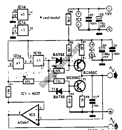
A highly accurate digital thermometer utilizing an LM35 probe with a resolution of 0.1 degrees Celsius. The circuit includes two adjustable components. The first, R5, is used to calibrate the display to zero. To perform this calibration, the end...
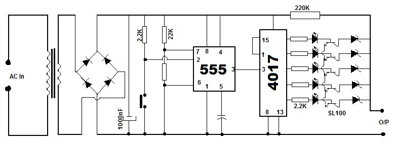
Battery eliminators are circuits that create a DC power supply from AC mains. Essentially, battery eliminator circuits consist of a step-down transformer, rectifier, and voltage regulator. A simple circuit of a multipurpose battery eliminator features various output voltage ranges...
This design outlines a simple 1 kHz square wave generator utilizing a few components and the LM3909 integrated circuit, which is beneficial for testing audio equipment. The circuit operates on a single 1.5V battery cell, producing a maximum output...
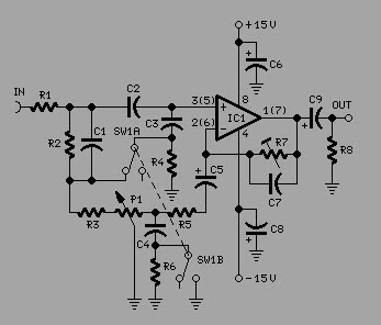
To achieve optimal audio reproduction at various listening levels, it is essential to incorporate tone-setting controls that align with the well-documented characteristics of human auditory perception. Specifically, human ear sensitivity exhibits a non-linear response across the audible frequency spectrum,...
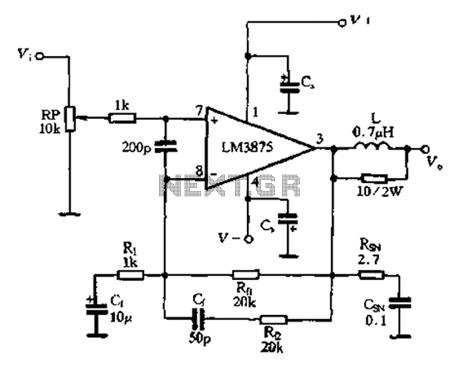
The 875T and LM3876T are high-performance 40W power amplifier integrated circuits (ICs). They operate within a frequency range of 20Hz to 20kHz with a continuous average power output under an 8-ohm load and exhibit a distortion level of only...
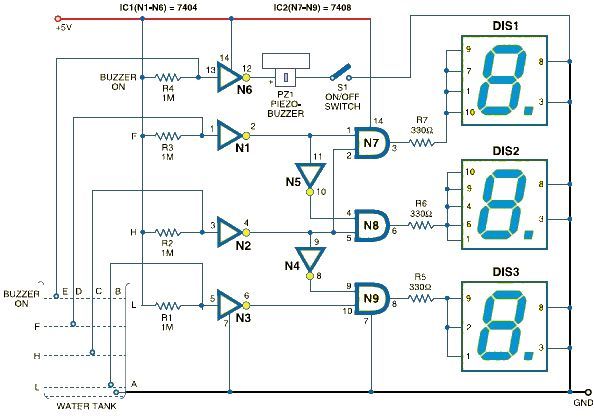
This schematic outlines a straightforward electronic project for designing a water level indicator circuit. It employs a 7-segment display to represent water levels in a tank as low, half, and full, indicated by the letters L, H, and F,...