
Digital thermometer circuit
The circuit design for the digital thermometer incorporates an LM35 temperature sensor, which outputs a linear voltage signal proportional to the temperature in degrees Celsius. The LM35 operates with a scale factor of 10 mV per degree Celsius, allowing for precise temperature readings. The circuit is configured to include a microcontroller or a display module to interpret the voltage signal from the LM35 and convert it into a readable temperature format.
The calibration process is critical for ensuring accurate readings. The adjustment of R5 to set the display to zero is essential for eliminating any offset errors that may occur in the measurement system. The grounding of R4 during this process ensures that the reference point for the voltage measurement is stable and accurate.
After calibration, the LM35 probe is connected to the designated terminals. The voltage output from the probe is then measured against the ground using a multimeter, which must be set to the appropriate range to capture the expected voltage output accurately. This step is crucial as it establishes the baseline for the temperature reading. The conversion of the voltage reading to temperature is straightforward; for instance, a voltage reading of 0.236 volts directly translates to a temperature of 23.6 degrees Celsius.
Once the initial measurement is taken, connecting terminal 1 of the LM35 to the circuit allows for continuous temperature monitoring. The adjustment of R7 fine-tunes the output to align with the measured value, ensuring that the displayed temperature is accurate.
This digital thermometer circuit is suitable for various applications where precise temperature measurement is required, including laboratory environments, HVAC systems, and general temperature monitoring tasks. The simplicity of the design, combined with the precision of the LM35 sensor, makes it an effective tool for accurate temperature readings.A very precise digital thermometer with LM35 probe (0, 1 degree of freedom). The circuit has two adjustments. One of them, R5, adjusts the displays to 0. To perform this, we have to connect the extreme part of R4 (that goes to the temperature probe) to the ground and we turn R5 until we see 0:0:0. Afterwards, we connect the probe LM35 to terminals 2 and 3 which are marked in the circuit. This is how we Then we measure the values between the non connected terminal, which is the out of the probe, and the ground, with the tester, adjusted to 1 Volt (bottom of the scale). The tension which is shown represents the temperature in the room. For example, if it marks 0. 236, the temperature is 23, 6 C. When we have the measure, we connect the terminal 1 of the probe to the circuit and we adjust R7 until it gives us the value of what we had measured.
🔗 External reference
Related Circuits

The circuit consists of a PIC microcontroller, an in-circuit serial programming (ICSP) interface, an RS232 level translator, and an HD44780 LCD display. Initially, a scrolling message is shown using the show_intro function. When a serial input is detected, the...
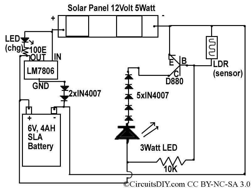
This document discusses a simple solar LED circuit. Solar panels range from 12 volts and 3 watts to larger sizes. To store energy, a 12-volt battery is required. The preferred choice is a sealed lead-acid (SLA) sealed maintenance-free (SMF)...

This circuit provides a visual 9-second delay using 10 LEDs before closing a 12-volt relay. When the switch is closed, the 4017 decade counter will reset to zero, illuminating the LED connected to pin 3. The output at pin...

Introduction The SP6648 integrated synchronous boost regulator is a compact circuit that provides ultra-high efficiency drive current for an LED flashlight using a Luxeon I light source. The circuit is configured to deliver a constant output current of 350mA...

The NE555 push-button delay lamp circuit is illustrated in Figure 3-5. This circuit features several components, including a power supply and relay control system. Typically, the switch SB and normally open relay contacts K1 are in an open state,...
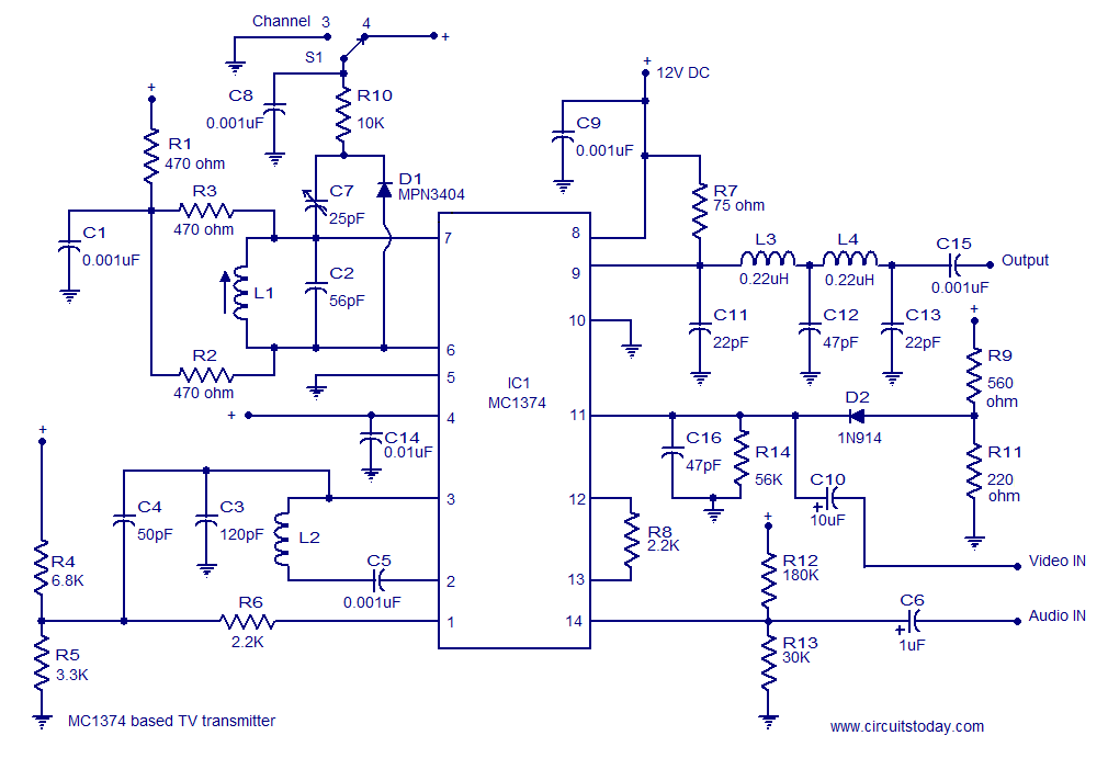
A simple TV transmitter circuit utilizing the TV modulator circuit IC MC1374. It operates with a 12V supply and is capable of broadcasting on channel 3 or 4, employing FM modulation for sound transmission. The TV transmitter circuit based on...
Warning: include(partials/cookie-banner.php): Failed to open stream: Permission denied in /var/www/html/nextgr/view-circuit.php on line 713
Warning: include(): Failed opening 'partials/cookie-banner.php' for inclusion (include_path='.:/usr/share/php') in /var/www/html/nextgr/view-circuit.php on line 713