
Smoke Detector Circuit
The optical smoke detector circuit utilizes a light bulb as a source of illumination and an LDR as a sensor. When smoke enters the detection area, it scatters the light emitted by the bulb, resulting in decreased light intensity reaching the LDR. The LDR's resistance varies inversely with the light intensity; thus, as the light intensity diminishes due to smoke presence, the resistance of the LDR increases. This change in resistance affects the voltage at the base of the transistor, which is configured to switch on the COB.
The COB serves as an indicator or alarm in this setup, and its operation is contingent on the transistor being activated by the voltage changes at its base. The circuit can be fine-tuned for sensitivity by adjusting VR1, which allows for customization based on the specific application or environment where the detector is deployed. The placement of the bulb and LDR is also critical; positioning them too far apart may result in insufficient sensitivity, while placing them too close may lead to false triggering.
To ensure reliable operation, it is advisable to conduct tests in various smoke conditions to calibrate the sensitivity accurately. Additionally, while this circuit can be a valuable tool for educational purposes and electronic projects, it should not replace conventional smoke detectors designed for residential safety.It relies on the smoke that is produced in the event of a fire and passes between a bulb and an LDR, the amount of light falling on the LDR decreases. This type of circuit is called optical smoke detector. Do not use it as a home smoke detector it`s jus for electronic projects. This causes the resistance of LDR to increase and the voltage at the b ase of the transistor is pulled high due to which the supply to the COB (chip-on-board) is completed. The sensitivity of the smoke detector depends on the distance between bulb and LDR as well as setting of preset VR1.
Thus by placing the bulb and the LDR at appropriate distances, one may vary preset VR1 to get optimum sensitivity. 🔗 External reference
Related Circuits
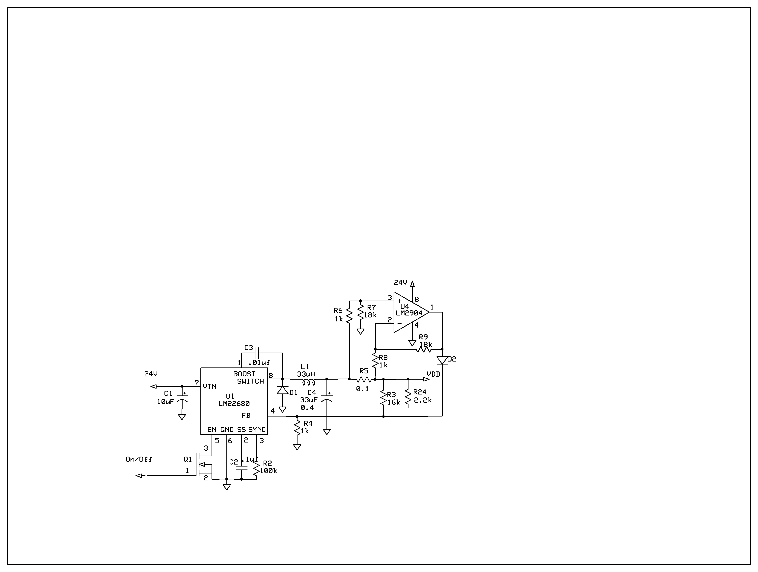
The product requires a voltage-controlled, current-limited power supply. Various switcher chips have been used with an op-amp to provide feedback for a current sense voltage to the feedback pin. Currently, an LM22680 is in use, but it has shown...

The Infrared IR Receiver circuit consists of a phototransistor, a microcontroller, and an amplifier. Understanding the data transfer between these three components is essential for successfully operating the circuit. The phototransistor receives digitally encoded data from an IR emitting...
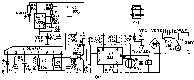
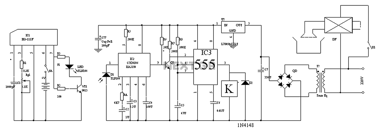
This circuit utilizes the KA2184 infrared receiver ASIC for an infrared remote control dimmer light application, as depicted in the schematic. The infrared signal is generated by a pulse generator using an NE555 timer integrated circuit. The NE555 produces...
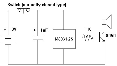
The M8031 circuit features an integrated RC oscillator and digital envelope circuits, which minimize the need for external components. It produces a sound that mimics a mechanical ding-dong. The M8031 operates with a low input voltage range of 1.3...
The circuit diagram for the automatic control of drinking fountains is presented below. The automatic control circuit for drinking fountains typically employs a combination of sensors and control elements to manage the operation of the fountain efficiently. The main components...
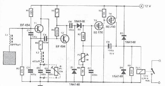
A simple proximity detector can be created using this electronic circuit. This circuit responds to the presence of a conductive object within a specific range. The sensitivity of the circuit can be adjusted with potentiometer P1 to achieve the...