
AC Current Monitor

The circuit utilizes a current sensing mechanism, which is critical for detecting the operational state of the electric heaters. A common approach for this is to use a current transformer or a Hall effect sensor that can be clamped around the power cable. This sensor is capable of generating a voltage signal proportional to the current flowing through the feeder.
The output from the current sensor is fed into a comparator circuit, which compares the sensor output against a predefined threshold voltage. When the current exceeds this threshold, indicating that the heaters are operational, the comparator output switches high. This transition activates a microcontroller or a transistor that drives an LED indicator.
The LED serves as a visual alert, indicating that the heaters are on. Additionally, the circuit may include a wireless transmission module, allowing real-time monitoring and notifications to be sent to a remote device, such as a smartphone or computer. This feature enhances the utility of the circuit, providing users with the ability to monitor the status of their heating devices from a distance.
Power supply considerations for this circuit must also be accounted for. A low-power design is recommended to ensure that the circuit can operate continuously without excessive energy consumption. The circuit can be powered using a small battery or a low-voltage AC power supply, depending on the installation environment.
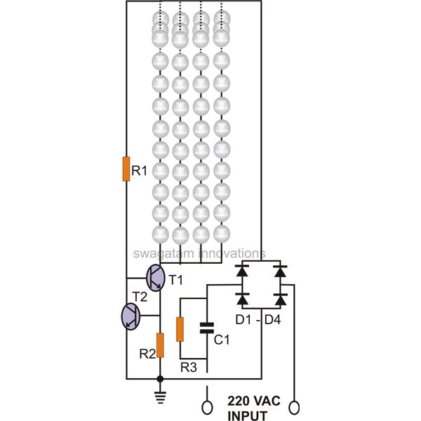
In summary, this remote monitoring circuit for electric heaters integrates current sensing, signal processing, and visual indication to provide an effective solution for ensuring safety and energy efficiency in heating applications.This circuit was designed on request, to remotely monitor when a couple of electric heaters have been left on. Its sensor must be placed in contact with the feeder to be able to monitor when the power cable is drawing current, thus causing the circuit to switch-on a LED.
🔗 External reference
Related Circuits
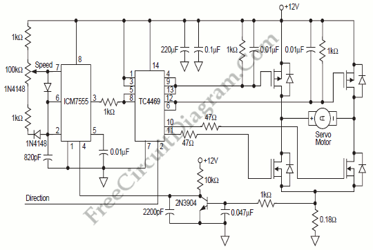
The circuit is designed to enable rapid changes in motor speed and direction by utilizing four outputs to drive a MOSFET H-bridge. The lower rail power MOSFETs are N-channel devices, while the upper rail MOSFETs are P-channel. All MOSFETs...
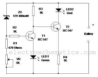
This circuit monitors the charging process of a 12 Volt Lead Acid or Tubular battery. The LED status indicates whether the battery is charging and signals when it reaches a full charge. It can be integrated into various battery...
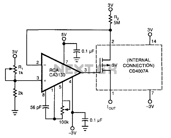
This circuit utilizes commonly available components to create a 0-to-200-nA current source. It incorporates a PMOS transistor from the input stage of a DC4007A, which is more accessible than a standalone PMOS transistor. The CA3130 operational amplifier functions as...
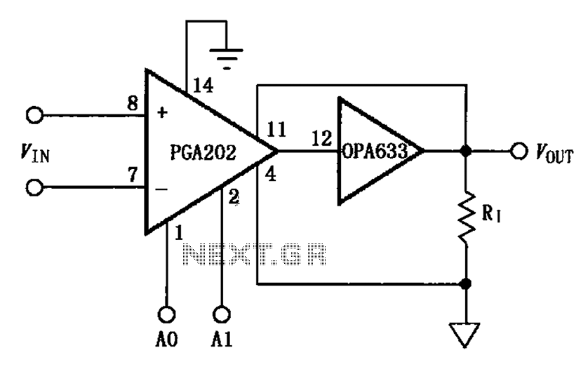
The figure illustrates a current boosting circuit configuration utilizing the PGA202 and OPA633 operational amplifiers. This circuit enhances the output current capability of the PGA202 operational amplifier, leveraging the performance characteristics of the OPA633 to achieve a higher output...
The circuit of a current-controlled LED tube light employs high-voltage transistors to implement the necessary current control operation based on a fundamental principle. A resistor (R2) is utilized to convert the increasing current into a voltage across itself. This...
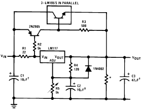
The following circuit diagram illustrates the application of the LM117 as a high current adjustable regulator. The LM117 is capable of supplying more than 1.5A. The LM117 is a popular adjustable voltage regulator that is designed to provide a stable...