
High Current Adjustable RegulatorCircuit Using LM117
The LM117 is a popular adjustable voltage regulator that is designed to provide a stable output voltage while allowing for high current output. It operates with an input voltage range of 4.25V to 40V and can be adjusted to output voltages from 1.25V to 37V. The device includes internal current and thermal limiting, making it robust for various applications.
In the circuit configuration, the LM117 is typically connected with two external resistors to set the desired output voltage. The resistors are connected in a feedback loop to the adjust pin of the LM117. The formula for calculating the output voltage (Vout) is given by:
Vout = Vref (1 + R2/R1) + Iadj * R2
Where Vref is the reference voltage (1.25V), R1 is the resistor connected from the output to the adjust pin, and R2 is the resistor connected from the adjust pin to ground. The term Iadj is the adjustment pin current, which is usually negligible in most applications.
To ensure stable operation, it is advisable to place bypass capacitors at the input and output of the LM117. A typical configuration includes a 0.1µF ceramic capacitor at the input and a larger electrolytic capacitor at the output to filter any voltage spikes and stabilize the output voltage.
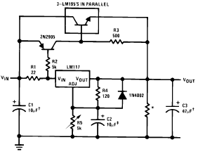
The LM117's ability to deliver up to 1.5A makes it suitable for powering various electronic devices that require a stable voltage supply under varying load conditions. The circuit can be further enhanced by incorporating additional features such as overvoltage protection and heat sinks to manage thermal dissipation, ensuring reliability and longevity in practical applications.The following circuit diagram shows the application of LM117 on High Current Adjustable Regulator. The LM117, is capable of supplying in excess of 1.5A over a.. 🔗 External reference
Related Circuits
This is a high-brightness LED driver circuit. To provide a constant-voltage output, DC/DC regulators are typically used. However, a constant-current output is the preferred method for driving LEDs. The high-brightness LED driver circuit is designed to efficiently manage the power...
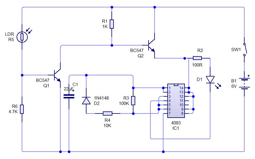
This is a simple experiment involving a Light Dependent Resistor (LDR) and a CD4093 integrated circuit. It modifies a previous dark sensor project that utilized two transistors. In this configuration, when light falling on the LDR is obstructed, the...
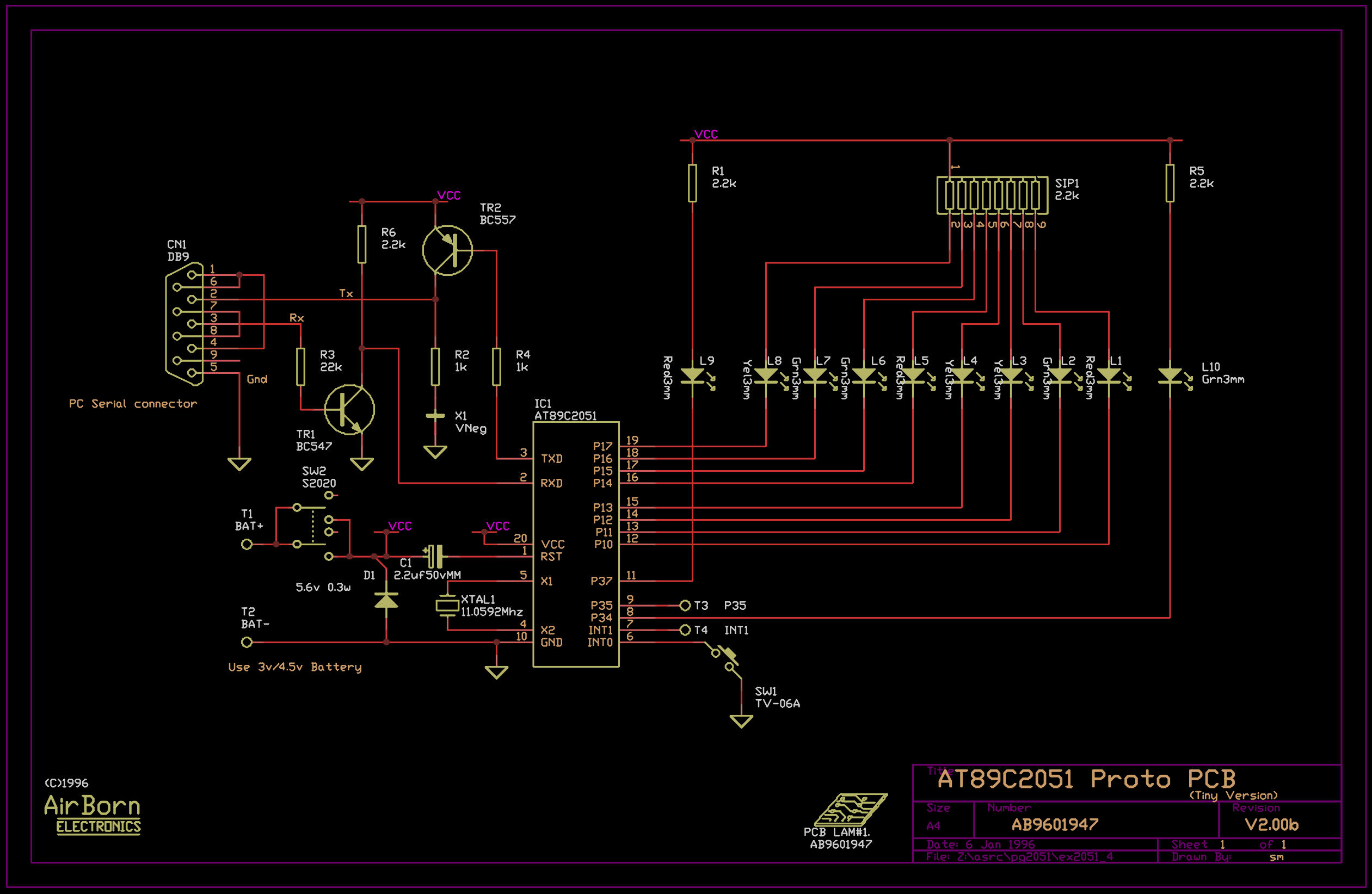
The example program included with the PG2051 evaluation kit is a basic serial to parallel converter written in 8051 assembler. This is probably a good example of the uses to which an AT89C2051 can be put - it would...
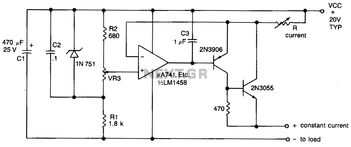
The output current is determined by the resistor R located in the collector of transistor Tr2. This resistor can be adjusted to provide a range of output currents from 100 mA to 2 A. Fine control is achieved through...
Some time ago, a 1-key keyboard project was developed. The ATTiny microcontroller has been a recurring consideration since then. The 1-key keyboard project utilizes the ATTiny microcontroller, a compact and efficient device suitable for a variety of embedded systems applications....
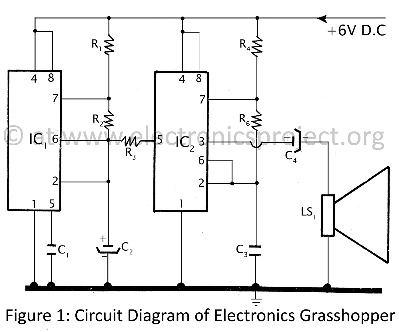
This project is designed for children and electronics beginners. It replicates the sound of a grasshopper or cockroach, producing a shrill noise at night. The circuit, referred to as the Electronics Grasshopper, generates a PI-PI sound and can function...