
AC Drill Speed Controller Circuit
The AC drill speed controller circuit is designed to modulate the speed of an AC-powered drill or borer, enhancing operational versatility and efficiency. The schematic typically incorporates a triac-based phase control method, which adjusts the power delivered to the motor by altering the phase angle of the AC waveform.
Key components of the circuit usually include a triac, a diac for triggering, resistors, capacitors, and a variable resistor (potentiometer) for speed adjustment. The triac serves as a switch that can control the current flow to the motor, while the diac ensures that the triac is triggered at the appropriate phase angle, thus controlling the effective voltage applied to the motor.
The circuit operates by allowing a portion of the AC waveform to pass through to the motor. By adjusting the potentiometer, the user can change the trigger point of the diac, which in turn modifies the phase delay, resulting in a variable speed output. This capability is particularly advantageous for tasks requiring different drilling speeds, such as when working with various materials or when precision is necessary.
Safety features may also be incorporated into the design, including fuses or circuit breakers to prevent overload conditions, as well as thermal protection to guard against overheating of the motor. Additionally, ensuring proper heat dissipation for the triac is crucial, often requiring a suitable heat sink.
Overall, this AC drill speed controller circuit schematic is a practical solution for enhancing the functionality of drilling equipment, making it suitable for a wide range of applications in both professional and DIY settings.This AC drill speed controller circuit schematic allows to control the holing speed of your borer or driller machine. This project is based on the fact tha.. 🔗 External reference
Related Circuits
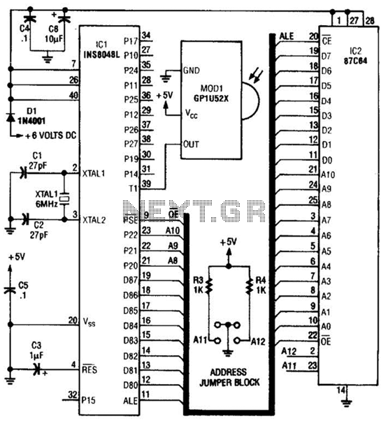
This circuit is based on the Sharp GP1U52X infrared module and the 1NS8048L microprocessor. The GP1U52X is a hybrid integrated circuit and infrared detector that provides a strong, clean signal for subsequent filtering and demodulation. The circuit utilizes the Sharp...

An audio power amplifier circuit for a 3-watt stereo amplifier using the MAX 7910 IC is explained below. The audio power amplifier circuit utilizing the MAX 7910 IC is designed to deliver a maximum output power of 3 watts per...
A varying brightness AC lamp circuit utilizes a silicon-controlled rectifier (SCR) to gradually adjust the intensity of a 120-volt light bulb by controlling the duration of AC line voltage applied to the lamp during each half cycle. The circuit...
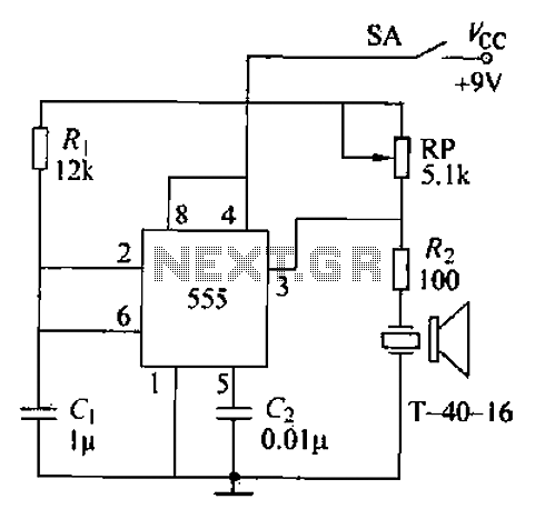
The circuit comprises an ultrasonic transmitter and a T-4 0-16 555 timer circuit. By adjusting the potentiometer RP, the frequency of the oscillation circuit can be modified. The circuit emits ultrasonic signals at a frequency of 40 kHz, with...
One of the critical components is a PWM speed controller, allowing for fine speed adjustments instead of just an "on" mode that runs at full power. This is important for safety. A basic stamp microcontroller was purchased, which includes...
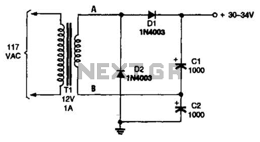
The voltage doubler consists of two diodes (D1 and D2) and two capacitors (C1 and C2), which are supplied by a 12-V, 1-A step-down transformer (T1). The voltage doubler circuit is designed to convert a lower input voltage into a...
Warning: include(partials/cookie-banner.php): Failed to open stream: Permission denied in /var/www/html/nextgr/view-circuit.php on line 713
Warning: include(): Failed opening 'partials/cookie-banner.php' for inclusion (include_path='.:/usr/share/php') in /var/www/html/nextgr/view-circuit.php on line 713