
AC LED drive circuit
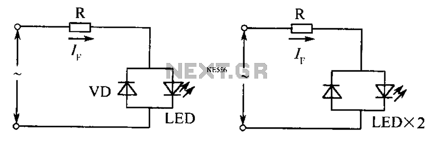
The described circuit is designed to accommodate both AC and DC power sources, ensuring reliable operation regardless of polarity. It incorporates a current limiting resistor, denoted as R, which plays a critical role in protecting the circuit from excessive current that could potentially damage components. The resistor's value is calculated in relation to the root mean square (RMS) voltage of the AC supply, which is essential for ensuring that the circuit operates within safe current limits.
In practical applications, the circuit can be employed in various devices where power supply polarity may be uncertain. This feature is particularly advantageous in environments where power connections may be made incorrectly, as it mitigates the risk of damage to sensitive electronic components. The design may also include additional protective elements such as diodes to prevent reverse polarity damage and to ensure that the circuit remains functional under varying conditions.
When designing the current limiting resistor, it is important to consider the maximum expected RMS voltage and the desired current limit for the application. The resistor value can be calculated using Ohm's law, where the resistance R is equal to the voltage (V) divided by the current (I). This relationship ensures that the circuit operates efficiently and safely, maintaining the integrity of both the power supply and the connected loads.
Overall, the circuit's ability to handle reversed polarity and its adaptability to both AC and DC drives make it a versatile solution in electronic design, suitable for a wide range of applications. As shown, still work in the case of unknown polarity of the voltage or the power supply polarity is reversed. And DC Drives as AC drives, the current limiting resistor R whose value is: where, AC RMS voltage.
Related Circuits
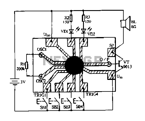
Constantly changing light and sound analog controller circuit 04 The circuit designated as the "Constantly Changing Light and Sound Analog Controller Circuit 04" is designed to modulate both light and sound outputs in a dynamic manner. This type of...
The circuit illustrated in Figure 2-48 consists of two configurations. Configuration 2-48 (a) operates using a 4.5V battery, while configuration 2-48 (b) employs AC capacitors to reduce the voltage supply. In configuration 2-48 (a), the delay time is influenced...
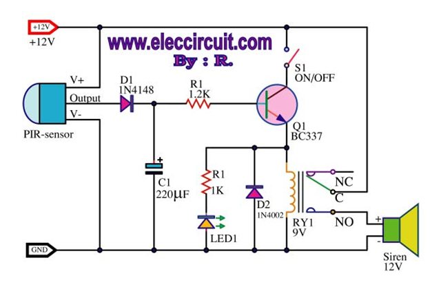
A motion detection alarm circuit utilizing a PIR sensor for motion detection. When movement is detected by the PIR sensor, it triggers a delay circuit, Q1, and other components. The motion detection alarm circuit is designed to provide an alert...
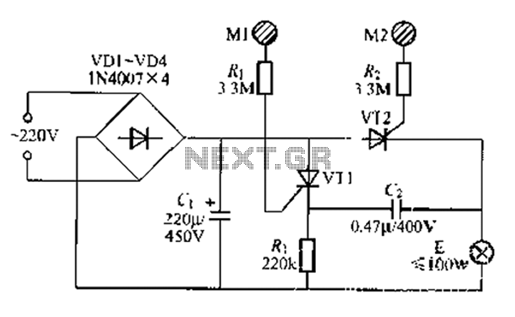
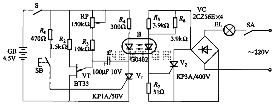
A circuit configuration features a relatively new strong key touch-state switch. Normally, the thyristors VT1 and VT2 are in the off-state, allowing minimal current to pass through the lamp F. At this point, the capacitance C comes into play....
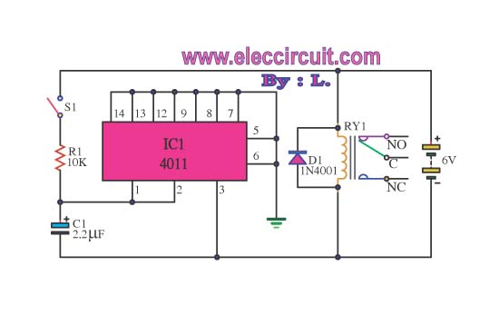
This circuit illustrates the use of the 4011 integrated circuit (IC) for a surge protection electronic circuit diagram. Features include the ability to delay the activation of other appliances connected to the output. The 4011 IC is a quad 2-input...
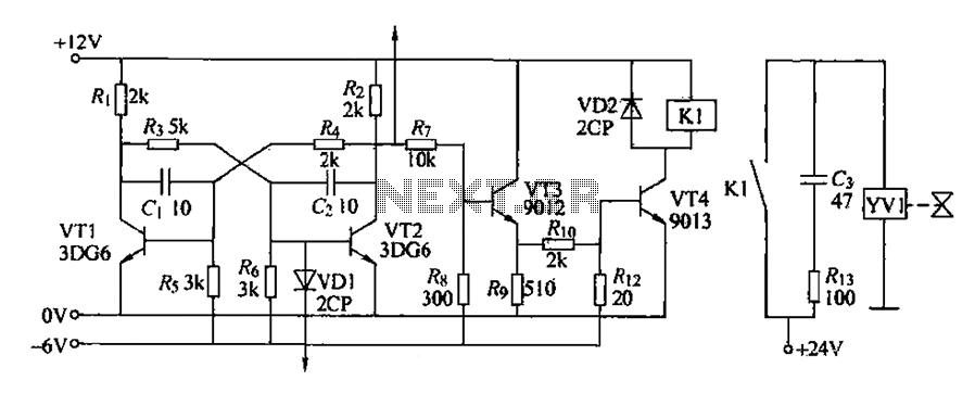
The circuit for detecting bad book binding is not illustrated. The solenoid valve is used to control the head of the YV1 mechanism for handling bad books. Under constant conditions, there is no positive signal indicating a bad book....
Warning: include(partials/cookie-banner.php): Failed to open stream: Permission denied in /var/www/html/nextgr/view-circuit.php on line 713
Warning: include(): Failed opening 'partials/cookie-banner.php' for inclusion (include_path='.:/usr/share/php') in /var/www/html/nextgr/view-circuit.php on line 713