
AC motor control circuit sprinkler
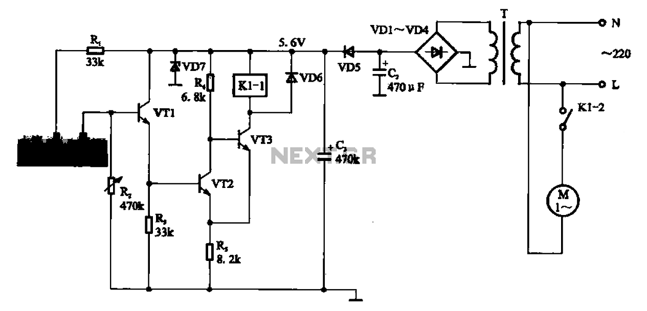
The AC motor control circuit for a sprinkler system is designed to regulate the operation of an AC motor, which drives the sprinkler mechanism. The circuit typically includes several key components: a power supply, a motor driver, control switches, and safety features such as fuses or circuit breakers.
The power supply provides the necessary voltage and current to the AC motor. It is essential to select a power supply that matches the motor specifications to ensure efficient operation. The motor driver is responsible for controlling the motor's speed and direction. This can be achieved through various methods, including using relays or solid-state switches.
Control switches are integrated into the circuit to allow the user to start or stop the motor and set the desired operating parameters. These switches can be manual or automated, depending on the system design. For instance, a timer switch can be used to activate the motor at predetermined intervals, facilitating automated watering schedules.
Safety features are critical in protecting both the motor and the circuit from overcurrent or short circuits. Fuses or circuit breakers should be strategically placed within the circuit to disconnect the power in the event of a fault, thereby preventing damage to the components.
The overall design of the AC motor control circuit should adhere to electrical safety standards and regulations, ensuring reliable operation while minimizing the risk of electrical hazards. Proper grounding and insulation are also vital to protect users and equipment from electrical shock.
In summary, the AC motor control circuit for a sprinkler system is a carefully designed assembly of components that work together to automate the watering process, ensuring efficiency and safety in operation.AC motor control circuit sprinkler If the circuit in the motor is an AC motor can be designed according to the circuit shown in FIG connection, work process and the principle o f the circuit with the procedure described above.
Related Circuits
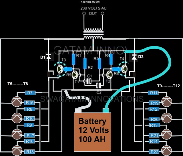
The current design of a power inverter offers an efficiency of approximately 85% and a power output exceeding 200 watts. This document provides a complete circuit schematic and detailed building procedure for a home-built power inverter. While numerous articles...
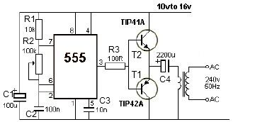
This 12V power inverter circuit can be utilized to power small devices that require 240 volts. It is particularly advantageous for operating 240-volt appliances using a 12-volt car battery. Unlike typical feedback oscillator inverters, this design employs a 555...

This 3V FM transmitter circuit is one of the simplest and most effective basic transmitters, offering a commendable transmitting range. It is remarkably powerful considering its small component count and 3V operating voltage. It can easily cover over three...
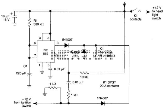
When the ignition switch is activated, relay K1 receives continuous power, allowing the headlights to be turned on. When the ignition is turned off, timer IC1 is activated, maintaining its power for a duration determined by resistor R1 and...

The device is referred to as the Itsy Bitsy USB Lamp. This concept is remarkably straightforward, raising the question of why it had not been conceived earlier. Originating as a student project at Massey University in Wellington, New Zealand,...
This capacitance meter circuit is similar to previous meter circuits, but it utilizes transistors instead of logic gates. A schematic diagram is provided. The capacitance meter circuit operates by measuring the capacitance of a capacitor through a time-based method. The...
Warning: include(partials/cookie-banner.php): Failed to open stream: Permission denied in /var/www/html/nextgr/view-circuit.php on line 713
Warning: include(): Failed opening 'partials/cookie-banner.php' for inclusion (include_path='.:/usr/share/php') in /var/www/html/nextgr/view-circuit.php on line 713