
Capacitance Meter Circuit Using Transistors
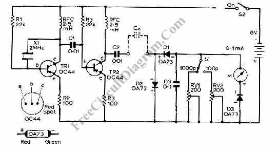
The capacitance meter circuit operates by measuring the capacitance of a capacitor through a time-based method. The core of the circuit consists of a transistor-based oscillator that generates a square wave signal. This square wave is used to charge and discharge the capacitor under test.
The circuit typically includes a few key components: a transistor (often an NPN type), resistors, a variable resistor (potentiometer), and a capacitor for timing purposes. The capacitor under test is connected in parallel with a timing capacitor, and the charging time of this combination is measured. The time taken for the voltage across the timing capacitor to reach a certain threshold level is directly proportional to the capacitance of the capacitor being tested.
In operation, the transistor is configured in a common-emitter configuration, which allows it to amplify the oscillation signal. The output frequency of the oscillator is influenced by the capacitance value of the capacitor being tested, which can be calculated using the formula derived from the RC time constant.
An additional feature of the circuit may include a digital display or analog meter to provide a visual representation of the capacitance value. Calibration of the circuit is essential to ensure accurate readings, which can be achieved by using known capacitance values to adjust the circuit parameters.
Overall, this transistor-based capacitance meter offers a reliable and straightforward method for measuring capacitance, making it a valuable tool for electronics enthusiasts and professionals alike.This capacitance meter circuit is similar with previous meter circuit, but it uses transistors rather than logic gates. Here is the schematic diagram: You. 🔗 External reference
Related Circuits
The input impedance of AC-coupled operational amplifier (op-amp) circuits is primarily determined by the resistance that establishes the DC operating point. When using CMOS op-amps, the input impedance is high, reaching up to 10 MΩ in current op-amps. For...
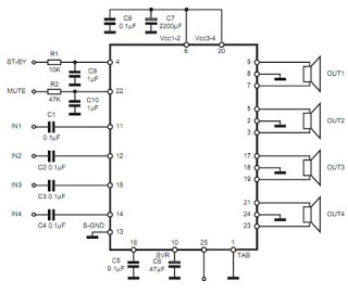
The TDA7383 features a fully complementary PNP/NPN output configuration, enabling a rail-to-rail output voltage swing without the need for bootstrap capacitors. This design significantly reduces the component count, allowing for compact assemblies. An integrated clipping detector facilitates gain compression...
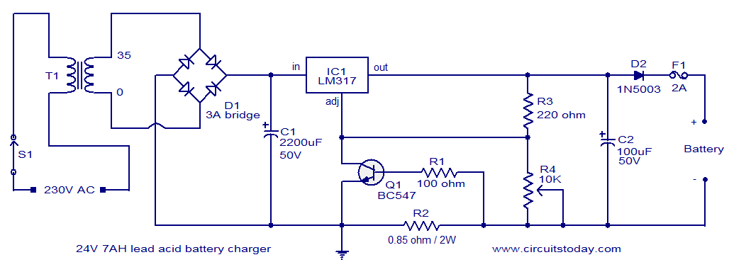
This lead-acid battery charger circuit is designed based on a request from Mr. Devdas C. His requirement was for a circuit that could charge two 12V/7AH lead-acid batteries connected in series. He did not specify the number of cells...
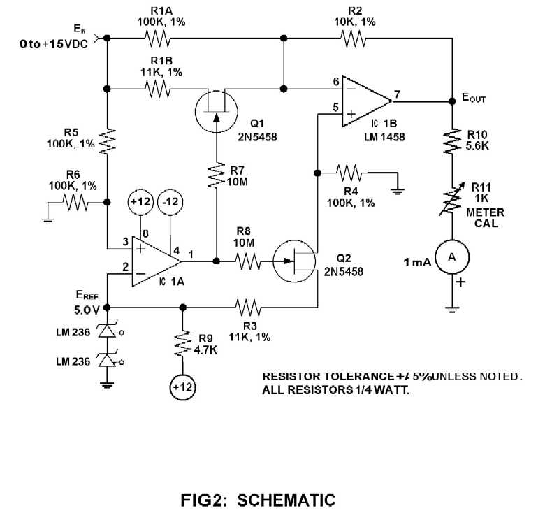
When using an analog meter to set the output of a power supply for testing 12-volt equipment, an expanded voltmeter scale offers significant advantages in accuracy compared to a linear scale. Figure 1 illustrates the original meter scale alongside...
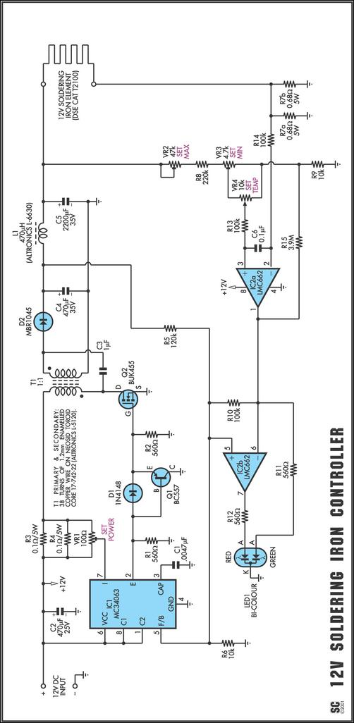
One reason commercial soldering stations are costly is that they typically require soldering irons with built-in temperature sensors, such as thermocouples. This circuit removes the necessity for a specialized sensor by detecting the temperature of a soldering iron heating...
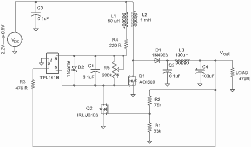
It employs a low threshold MOSFET and two coupled coils to function as a joule thief. An additional MOSFET is utilized for regulation. The circuit operates as a joule thief, which is a type of DC-DC converter designed to extract...