
Cookers detection control circuit
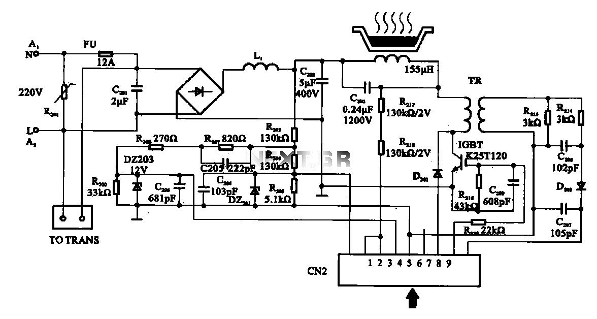
The cooker detection control circuit operates by utilizing an inductance coil and a resonant capacitor to create a high-efficiency heating mechanism. The inductance coil, typically rated at 150 µH, is coupled with capacitor C203, which is rated for high voltage (1200 V) to withstand the resonant voltage during operation. The circuit begins with an AC input of 22 V, which is converted to DC using a bridge rectifier. The resulting DC voltage of 30 V is applied to the stove hob coil, which generates a magnetic field necessary for induction heating.
The interaction between the stove plate coil and the gate control mechanism is crucial for regulating the current flow. When the gate control is activated, it allows current to pass through the coil, generating high-frequency oscillations. These oscillations increase the efficiency of heat generation, making the cookers more effective in cooking applications.
Protection features are integrated into the circuit design to ensure safe operation. The varistor R201 is a voltage-dependent resistor that acts as a protective device, short-circuiting when the input voltage rises above a predetermined threshold, thus preventing damage to the circuit components. The inclusion of a fuse (FU) further enhances safety by disconnecting the circuit in case of excessive current, thereby protecting against potential hazards.
Overall, the cooker detection control circuit exemplifies a well-designed system that combines efficient heating technology with robust safety measures, making it suitable for modern cooking applications.Cookers detection control circuit The control circuit shown in cookers for testing. Inductance coil disc lesion is generally about 150 pH. Stove plate coil and capacitor resona nt device C203, C203 resonance when the resonance voltage generated is relatively high, so the C203 is a high voltage capacitor voltage is 1200 V. AC 22V voltage through a bridge rectifier into a heap on the DC 30V plus stove hob coil, the coil plate to provide a bias for the stove.
Current flows through the coil plate stove, the mutual inductance transformer after arrival gate Control. Control of the gate is turned off will make the disc lesion in the coil currents pass, off the change, the formation of high-frequency oscillations.
High-frequency oscillations of current to the heat generating efficiency cookers improved. L, N terminal then two 22V AC input, the loop voltage protection varistors R201 play the role, that is, when the input voltage is too high, the varistor R201 will play a short-circuit protection. In the circuit also has a fuse FU. When the machine current is too large, FU will fuse, which is a means of protection. Therefore, the input into the overvoltage protection circuit portion is usually provided a device and a overcurrent protection devices.
Related Circuits
A 2 µF capacitor is charged to approximately 340 volts, and the discharge is controlled by a silicon-controlled rectifier (SCR). A Schmitt trigger oscillator (74C14) and a MOSFET (IRF510) are utilized to drive the low-voltage side of a small...
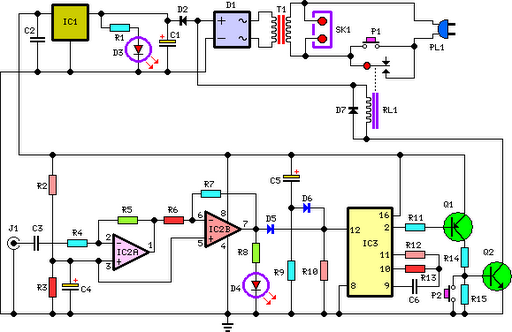
This circuit deactivates an amplifier or any connected device when a low-level audio signal at its input is absent for at least 15 minutes. Pressing P1 turns the device on, supplying power to any appliance connected to SK1. The...
This little guide for every electronics tester would actually have to lie in the toolbox. You can have components such as resistors, capacitors, diodes, etc. of testing. T1 and T2 form a Darlington. Therefore only need a small base...
The two circuits below illustrate the application of the 555 timer to activate a relay for a specified duration by pressing a momentary normally open (N/O) push button. The circuit on the left can be used for longer time...
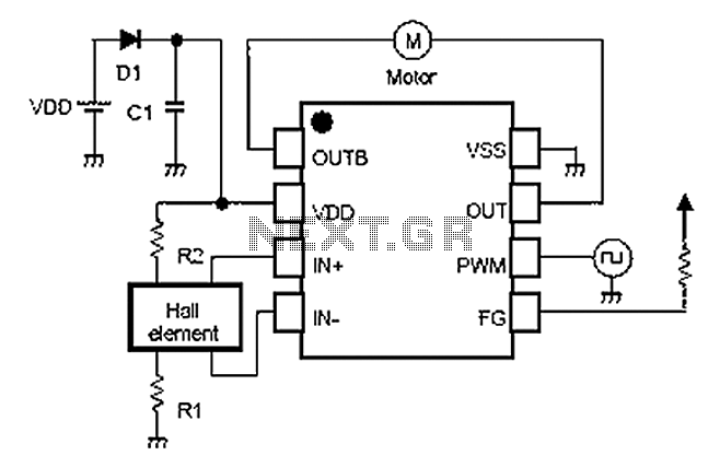
A simple single-phase brushless DC motor drive using the NJU7365 motor driver IC from New Japan Radio Co., Ltd. The NJU7365 is designed for single-phase motor applications and features built-in MOSFET motor drives, direct PWM input, FG output, and...
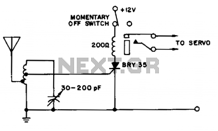
A simple and effective receiver for actuating garage doors, alarms, warning systems, etc. The SCR, which has a very low trigger current of 30 µA, requires an input power of only 30 µW to activate the relay. A high...