
relay Do I need a protection diode here
In the described automotive relay circuit, the relay serves as a crucial component for controlling various electrical functions in the vehicle, often acting as a switch for high-power devices while being controlled by low-power signals. The B/G line functions as a safety feature, ensuring that the relay does not activate under high engine temperature conditions. This is a common protective measure in automotive applications, designed to prevent potential damage to the engine or related systems.
The proposed modification involves cutting the L line, which is typically responsible for energizing the relay. By inserting a device that utilizes logic gates, the intention is to create a more sophisticated control mechanism. Logic gates will process input signals based on predefined conditions, allowing for the relay to be energized only when all necessary criteria are satisfied. An output transistor will act as a switch, connecting the L line to ground when the conditions are met, thus energizing the relay.
The consideration of a protection diode is critical in this circuit design. A diode placed across the relay coil can serve to protect the output transistor from voltage spikes generated when the relay coil is de-energized. These spikes, known as back EMF (electromotive force), can potentially damage the transistor if not properly mitigated. The presence of the diode should not interfere with the logic implemented by the combination of L, L/B, and B/G, provided that the diode is correctly oriented. It will allow current to flow in the reverse direction only when the relay is turned off, effectively clamping the voltage to a safe level and protecting the transistor.
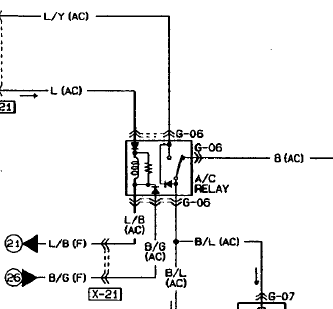
In summary, the integration of logic gates and a transistor to control the relay adds complexity and functionality to the circuit, enhancing its operational reliability. The careful placement of a protection diode can further safeguard the components, ensuring that the system operates within its designed parameters without compromising the logic control established by the existing circuitry.I have an automotive relay (from a scan of a workshop manual I`m afraid) which is rather more complexly wired up than the relays I`m familiar with. In this diagram: B/G - holds high if another condition is met (engine temp too high), to prevent the relay energising.
(As far as I can tell. this is the correct logic for sure, not sure if it tech nically works that way!) I understand how the relay works at the moment. However, what I plan is to cut (L) and insert a device which will prevent the relay energising unless some further conditions are met. This is achieved with some logic gates and an output transistor, which will `join` L when my device allows it.
What I can`t tell is if I need a protection diode across the relay to protect my transistor And if I do, would this interfere with the logic provided by the combination of L, L/B and B/G 🔗 External reference
Related Circuits
Bold lines indicate soldered connections, while arrows represent wire-based connections. Red indicates V_cc, black represents ground, blue signifies intermediate connections, and gold denotes the primary output. Pins 1 and 5 are connected to ground. It is noted that pin...

A photodiode can be utilized for high-speed digital transmission; however, it is necessary to provide a high-speed signal conditioner for this purpose. The amplifier circuit... A photodiode is a semiconductor device that converts light into electrical current. In high-speed digital...

This photodiode-based alarm system is designed to provide a warning signal when an individual passes through a designated protected area. The circuit remains in standby mode by utilizing a laser beam or infrared (IR) beam directed onto the photodiode....
Here's a power-on time delay relay circuit that takes advantage of the emitter/base breakdown voltage of an ordinary bi-polar transistor. The reverse connected emitter/base junction of a 2N3904 transistor is used as an 8 volt zener diode which creates...
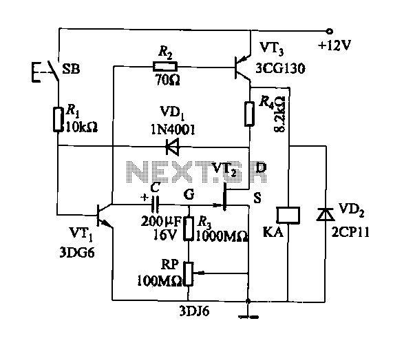
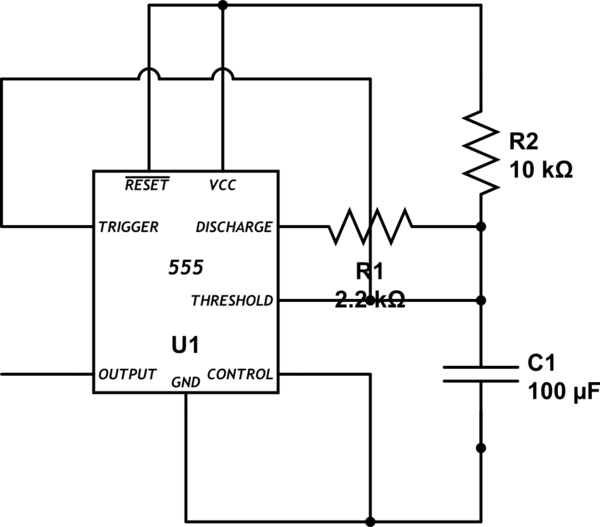
Discharge time relay circuit. The timer utilizes a field effect transistor, providing high timing accuracy and extended timing capabilities. With R3 set to 1,000,000 ohms and C at 200 microfarads, a delay time of 8 hours can be achieved....
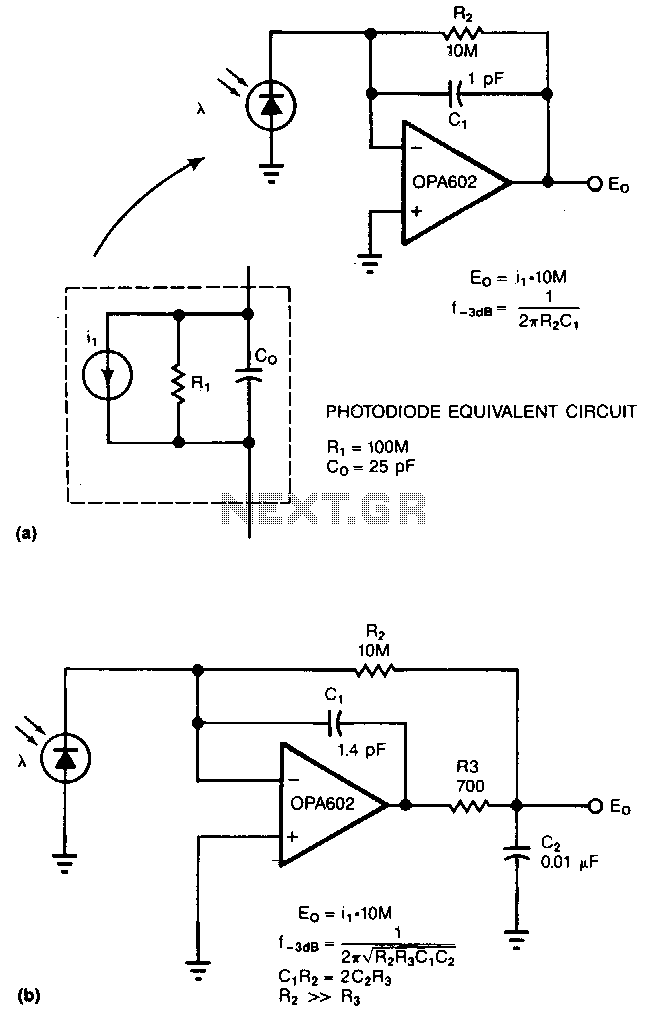
Adding two passive components to a standard photodiode amplifier reduces noise. Without the modification, the shunt capacitance of the photodiode reacting with the relatively large feedback resistor of the transimpedance (current-to-voltage) amplifier creates excessive noise gain. The improved circuit...