
AC-static SPDT switch
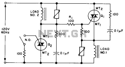
An SPDT (Single Pole Double Throw) solid-state relay is a crucial component in electronic switching applications, enabling control over multiple loads with a single control signal. In this configuration, the relay consists of two main transistors, Q1 and Q2, along with resistors and a switch.
Upon the application of voltage to the relay, Q1 is triggered, allowing current to flow and energizing load #1. The presence of full line voltage across Q2 is essential for this operation, as it ensures that gate current flows through resistor R1, maintaining Q1 in an 'on' state. R1 serves as a gate resistor, limiting the current to Q1 and protecting it from excessive current that could lead to damage.
The operation of the relay can be altered by the position of switch S1. When S1 is closed, it activates Q2, which in turn removes the gate drive from Q1. This action effectively deactivates load #1, as Q1 turns off, and simultaneously activates load #2. This switching mechanism allows for seamless transition between loads, making the circuit versatile for various applications.
The relay's design ensures that it can handle the necessary voltage and current levels for both loads while providing isolation between the control circuit and the load circuit. This isolation is critical for protecting sensitive control electronics from high voltages or currents present in the load circuits. The use of solid-state components also contributes to faster switching times and increased reliability compared to traditional electromechanical relays.
In summary, the SPDT solid-state relay provides an efficient means of controlling multiple loads with a single control input, utilizing the properties of transistors to achieve rapid and reliable switching. Properly designed, this relay configuration can enhance the functionality and safety of various electronic systems.An SPDT solid state relay is shown. When voltage is applied Ql will turn on, activating load #1, because the full line voltage appears across Q2, supplying gate current through Rl. When SI is closed. Q2 turns on removing the gate drive from Ql and activating load #2. 🔗 External reference
Related Circuits
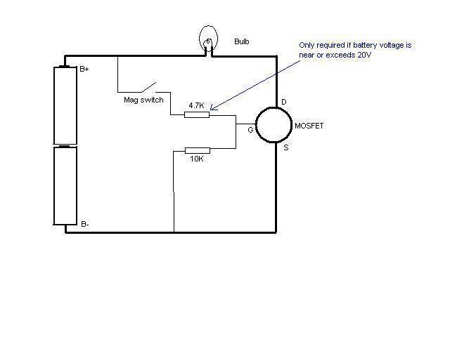
In this schematic provided by Jimmy M, will this circuit drain the batteries when the light is not in use? There is consideration for building a MOSFET circuit to be used in a compact application, where the original bulky...
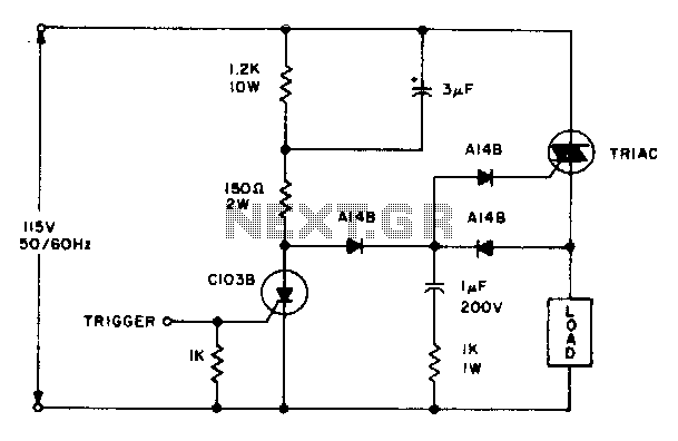
The triac will be activated at the beginning of the positive half cycle due to the current flowing through the 3 µF capacitor, provided that the C103 SCR is in the off state. The load voltage subsequently charges the...
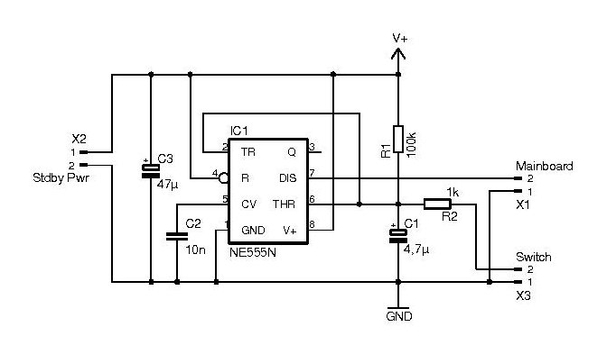
Automatic power switch for ATX power supplies. Visit the page to read the explanation about the related circuit diagram. The automatic power switch for ATX power supplies is a circuit designed to manage the power-on and power-off states of an...
This is a clap switch designed to avoid false triggering. To activate or deactivate any appliance, a user must clap twice. The circuit changes its output state only when two claps are detected within a specified time frame of...
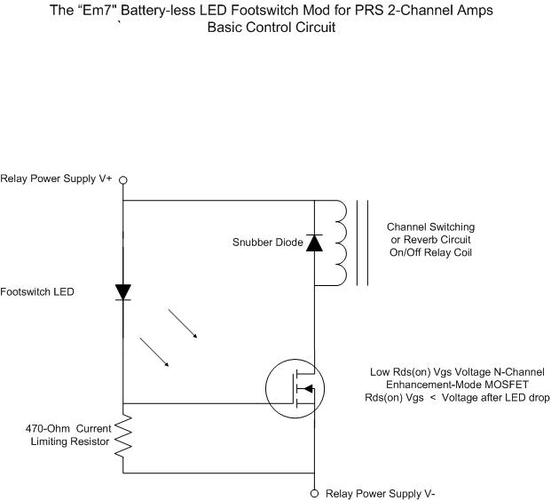
For individuals seeking LED-based footswitching without the inconvenience of battery installation, a battery-less LED-based footswitch modification is being developed for 2-channel amplifiers. This solution is designed to work with the existing TRS jack and footswitch, and it will involve...
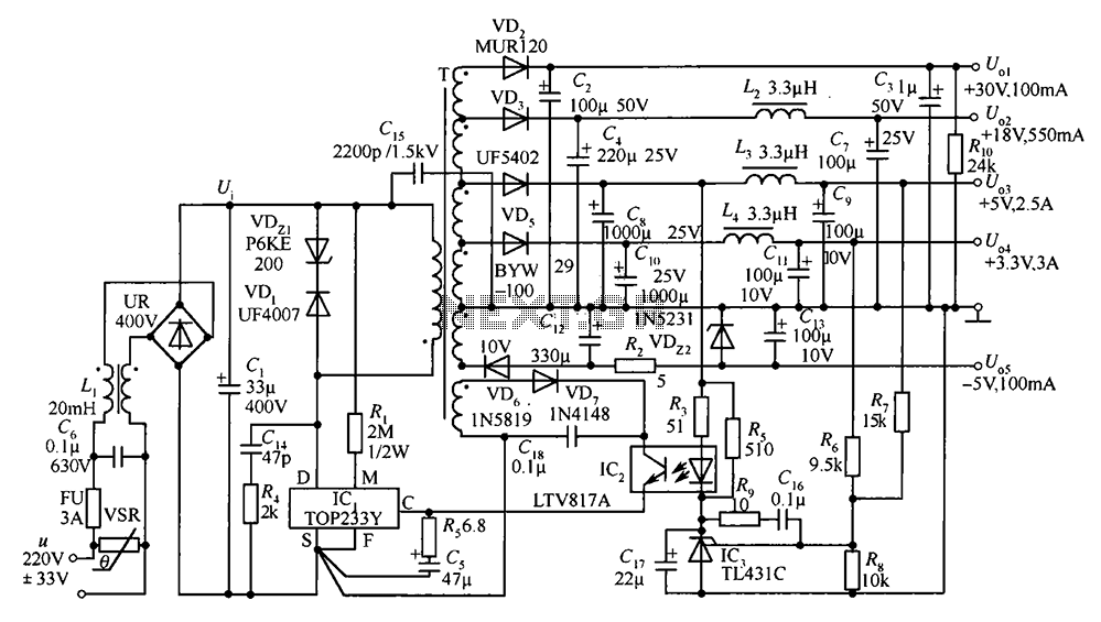
A 35W switching power supply circuit designed for a set-top box output is depicted in Figure 5. It features five distinct voltage outputs: Uo1 (+30V, 100mA), Uo2 (+18V, 550mA), Uo3 (+5V, 2.5A), Uo4 (+3.3V, 3A), and Uo5 (-5V, 100mA)....