
automatic power switch for atx power supplies

The automatic power switch for ATX power supplies is a circuit designed to manage the power-on and power-off states of an ATX power supply unit (PSU). This circuit typically integrates a relay or a transistor switch, which is controlled by a microcontroller or a simple logic circuit that detects the presence of a power signal. When the system is powered on, the automatic switch engages the relay or transistor, allowing power to flow from the PSU to the connected components.
The circuit diagram generally includes the following key components:
1. **Power Supply Input**: The ATX power supply input typically consists of a 24-pin connector that provides various voltage rails (3.3V, 5V, 12V, etc.) to the motherboard and peripherals.
2. **Control Circuit**: This section may include a microcontroller or comparator that monitors the power-on signal from the motherboard or a manual switch. The control circuit determines when to activate the relay or transistor based on the input signal.
3. **Relay or Transistor Switch**: The relay or transistor acts as the main switching element. When activated, it connects the power supply output to the load, allowing the system to power on. The relay must be rated to handle the current and voltage of the power supply.
4. **Protection Components**: Additional components such as diodes may be included to protect against back EMF from the relay coil and to ensure safe operation. Fuses or circuit breakers can also be integrated for overload protection.
5. **Indicator LEDs**: Optional LEDs can be added to provide visual feedback on the status of the power supply, indicating whether the system is powered on or off.
In summary, the automatic power switch for ATX power supplies enhances the usability and functionality of computer systems by providing a seamless power management solution. The schematic design ensures reliability and safety while accommodating various power requirements of modern electronic devices.Automatic power switch for ATX power supplies power supply. Go to that page to read the explanation about above power supply related circuit diagram. 🔗 External reference
Related Circuits
This circuit is essentially a crystal radio equipped with an audio amplifier that demonstrates considerable sensitivity, successfully receiving multiple strong stations in the Los Angeles area using a minimal 15-foot antenna. Employing a longer antenna can enhance signal strength;...
This contributed project is a result of considerable collaboration between Sergio and myself, and should not be seen as necessarily a complete project in itself, but a stepping stone to understanding switching power supplies, how they work, and what...
Access to the resistors was available, and measurements indicated an open circuit when disconnected from any ground or input source. The circuit in question involves resistors that have been verified for accessibility. When measured in isolation—meaning they are not connected...
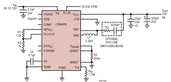
A very simple, high-efficiency switching mode buck-boost power supply circuit can be designed using the LTM4609 switching regulator IC. This circuit will provide a fixed output voltage of 12 volts. As illustrated in the schematic, the switching power supply...
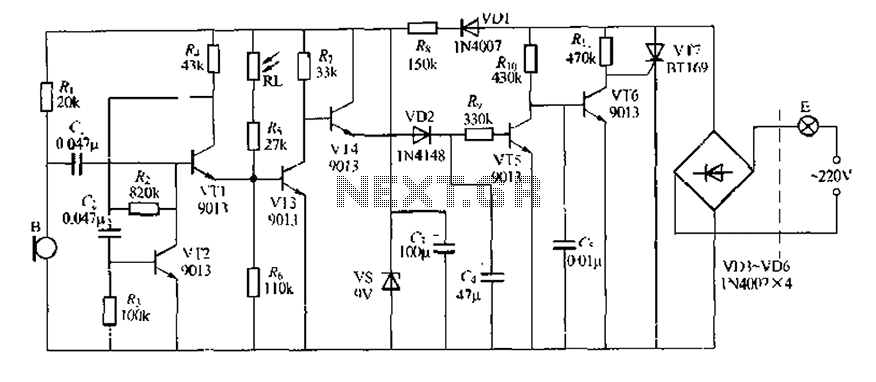
This circuit design is a sound and light control delay switch for staircase walkway lighting, featuring high voice sensitivity. In the evening, when someone walks on the stairs, their footsteps activate the electronic meter, turning on the lights. If...
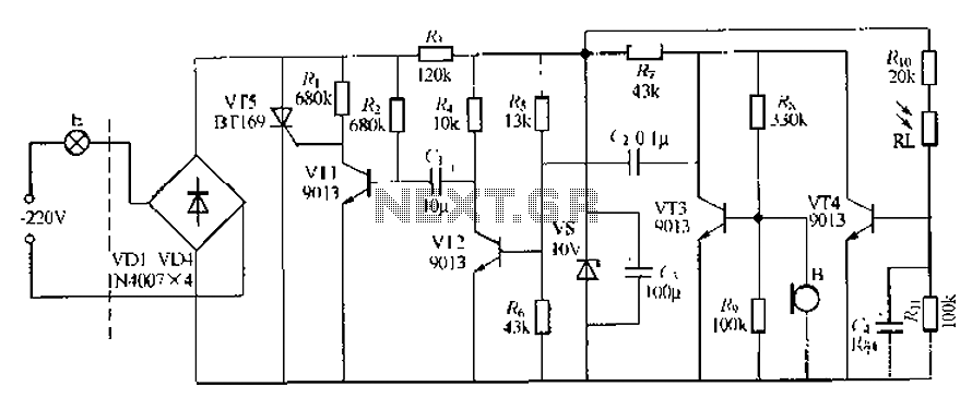
This circuit describes a sound and light control delay system for a walkway stairs light switch. It involves various components including 220V AC electric bulbs, diodes (VD1-VD4), and resistors. The circuit utilizes a rectifier regulator to stabilize the voltage...