
ac switching question
The AQV20 series solid-state relay is designed to handle AC loads efficiently, making it a suitable choice for controlling AC relay coils. Its configuration includes a MOSFET in series with a diode, which serves to protect the circuit from reverse voltage spikes generated when the relay coil is de-energized. This feature is critical, as inductive loads can create significant back EMF, potentially exceeding the voltage ratings of components in the circuit. The recommendation to include back-to-back Zener diodes across the relay coil adds an additional layer of protection, ensuring that any voltage spikes are clamped to safe levels.
The SSR's isolation from the power line is a significant advantage, providing safety and preventing noise from affecting the control circuit. The requirement for a small DC current for activation allows for flexibility in control circuit design, but care must be taken to include a current-limiting resistor to avoid exceeding the input control diode's maximum ratings. This precaution is essential in ensuring the longevity and reliability of the SSR.
When considering the MOCZ500 optoisolator, the concern about its current rating is valid. With a maximum current limit of 500mA and a measured coil draw of 465mA, the operating margin is minimal. This proximity to the limit could lead to reliability issues under varying load conditions. The unavailability of the MOCZ500 may necessitate the search for alternative components that can provide similar functionality without compromising performance.
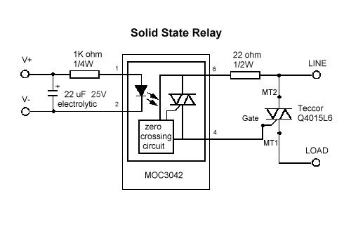
The discussion regarding zero-crossing circuitry and inductive loads highlights the importance of understanding the phase relationships in AC circuits. While the zero-crossing feature is beneficial for timing the turn-on of the load, it does not negatively impact the turn-off process. TRIACs and SCRs naturally turn off when the current through them drops to zero, which is a critical characteristic when switching inductive loads. As a result, the design can incorporate zero-crossing control without fear of generating harmful transient voltages, ensuring stable operation in applications involving solenoids or other inductive devices.The AQV20 series should be fine to drive an A. C. relay coil if the de-energizing back EMF from the relay coil does not exceed 600 v rating. It is diode in series with a conducting MOSFET. Might want to add two back to back zener surge suppressors across relay coil to be sure. That SSR should work fine for you application. It`s input is isolated fr om the power line and just requires a small DC current to turn on (make sure you use a current limiting input resistor or you will blow the input control diode). The AQV20 series should be fine to drive an A. C. relay coil if the de-energizing back EMF from the relay coil does not exceed 600 v rating. It is diode in series with a conducting MOSFET. Might want to add two back to back zener surge suppressors across relay coil to be sure. You should not need any suppressors since a TRIAC automatically turns off when the current through the inductor goes to zero.
There thus will be no back EMF. In regards to the MOCZ500, isn`t there some no-no about using zero crossing circuitry with inductive loads like a solenoid It had to do with the current and voltage being out of phase, but I couldn`t really get my mind around why. Also, I measured the largest amp draw coil I am to switch, and it was drawing 465mA. If I were to use the MOCZ500, which has a current limit of 500mA, am I not giving the SSR enough room to operate reliably After looking around a bit, it seems that the MOCZ500 rights were sold from motorola to fairchild, but fairchild doesn`t even list it as a valid part on their website.
It may be falling into the nether regions of part availability. Anybody know of a similar part In regards to the MOCZ500, isn`t there some no-no about using zero crossing circuitry with inductive loads like a solenoid It had to do with the current and voltage being out of phase, but I couldn`t really get my mind around why. A zero-crossing circuit only affects the timing of the device turn-on (which, of course, occurs at the voltage zero crossing).
It has no effect on the turn-off which occurs naturally at the zero current crossing for all TRIACs and SCRs. It either case I see no problem with driving an inductive load with this. Turning on an inductor at zero crossing certainly has no adverse effect, and turning off the solenoid at zero current generates no transient voltages.
🔗 External reference
Related Circuits
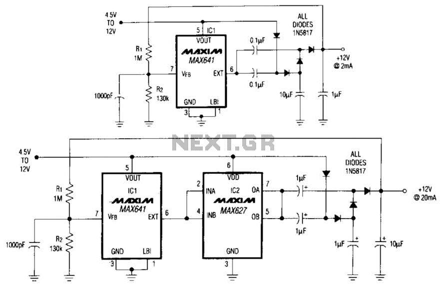
In conventional applications, switching-regulator integrated circuits (ICs) regulate the output voltage (VQVT) by controlling the current through an external inductor. However, the IC in configuration A utilizes a diode-capacitor network in place of the inductor, providing comparable performance for...
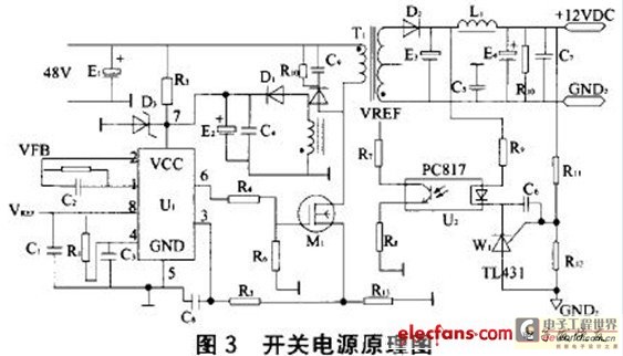
The motor vehicle currently represents a no-emission automotive solution, serving as a green means of transportation that is expected to significantly impact human society in the 21st century. The direct-flow brushless electric machine has emerged as a leading technology...
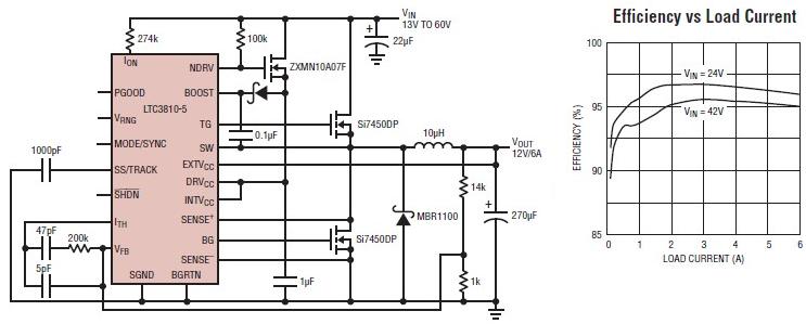
The LTC3810-5 synchronous step-down switching regulator controller can be used to design a simple and efficient 12-volt switching power supply electronic project with minimal external components. This controller is capable of stepping down voltages from up to 60V, making...
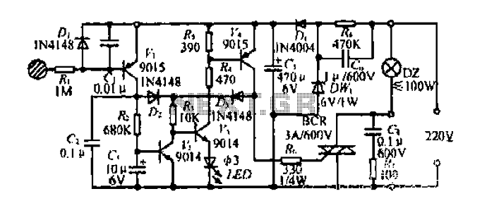
Diagram 2 depicts a shake tube circuit with a capacitance (C) and a trigger voltage rectifier filter element. The circuit includes a trigger voltage transistor amplifier (H), three pull tubes (n, U, v), and utilizes a thyristor as a...
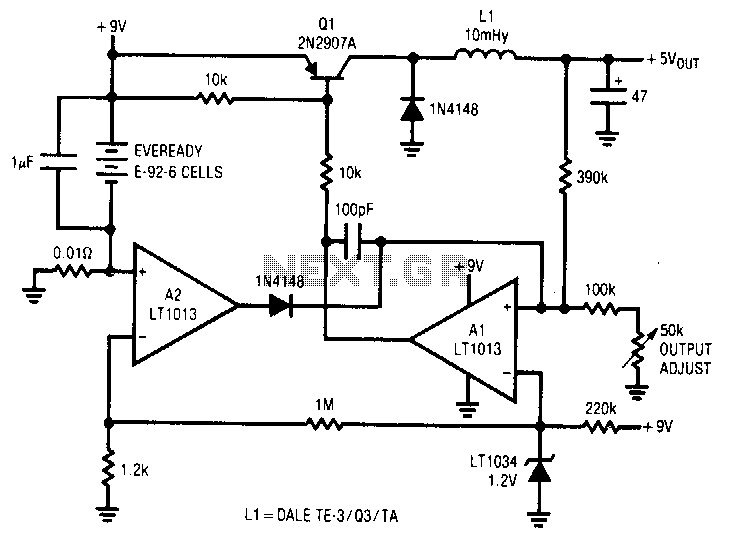
A simple battery-powered switching regulator provides 5 V output from a 9-V source with 80% efficiency and a 50 mA output capability. When Q1 is activated, its collector voltage increases, allowing current to flow through the inductor. This causes...
This circuit is designed to double nearly any DC input voltage while handling a substantial amount of current. For instance, it can work with input voltages ranging from 12 to 24V. With minor modifications, it can also provide any...
Warning: include(partials/cookie-banner.php): Failed to open stream: Permission denied in /var/www/html/nextgr/view-circuit.php on line 713
Warning: include(): Failed opening 'partials/cookie-banner.php' for inclusion (include_path='.:/usr/share/php') in /var/www/html/nextgr/view-circuit.php on line 713