
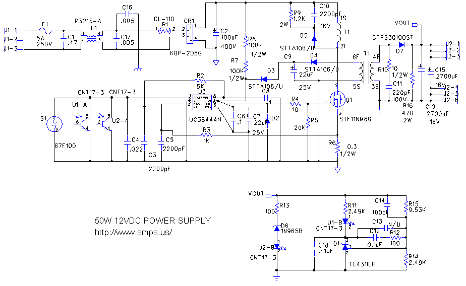
switching power supply 2
This circuit description outlines a versatile DC-DC converter that can be tailored to various voltage requirements and applications. It employs a flyback converter topology, which is particularly advantageous for battery charging and LED drive applications due to its efficiency and flexibility in handling different input voltage ranges. The use of a current-mode controller ensures that the output current remains within safe limits, protecting both the circuit and the load. The integration of feedback mechanisms allows for precise voltage regulation, making this circuit suitable for sensitive electronic applications where stability is crucial. The combination of a diode-capacitor network in place of traditional inductive components further enhances the design's adaptability, enabling it to meet the demands of diverse electronic systems while maintaining efficiency and performance standards. Overall, this circuit serves as a reliable solution for applications requiring increased voltage from lower DC sources, making it an invaluable tool in the field of electronics.This circuit will double almost any DC input voltage as well as handling plenty of current. 12 to 24V is just an example. With a few changes, it can also supply any desired output voltage. There are many possible applications. One I can think of would be to get the 28V for the ADC connector on Gigabit Ethernet and later Power Macintosh G4s from th e +12V on a standard PC ATX power supply. Basically any time you need more voltage than what you`ve got. Possibly on camping trips when you need 12-14 volts but only have 6V cells. Also you can use it to boost the cooling power of the fans in your computer if they can handle the extra voltage. Some can`t. Keep reading for more on this. What I use it for is to increase the speed and thus the airflow of a standard 80mm DC brushless fan. White-LED backlights are gaining acceptance because they offer higher reliability and simpler drive circuitry than those based on CCFL and EL technology.
As a result, the white-LED backlight is increasingly common in PDAs, cell-phones, digital cameras, and other portable devices. A design in which the display is backlit (or frontlit) for extended periods needs an efficient circuit that drives the LEDs with a controlled current, and eliminates the wasted power associated with current-limiting resistors.
A flyback converter implements a current-limited power supply to charge lead-acid batteries. The MAX773 current-mode controller limits the output current and the flyback transformer provides isolation and flexibility for input voltages both above and below the battery voltage. The MAX471 current-sense amplifier monitors the charging current and feeds back to a threshold detector so that below a designed threshold the flyback converter can switch to a lower charging voltage for trickle-charge mode.
The circuit shown in Figure 1 charges lead-acid batteries in the conventional way: A current-limited power supply maintains a constant voltage across the battery (2. 4V/cell or so, as specified by the battery manufacturer) until the charging current decreases below a current threshold defined by the capacity of the battery.
At this point, the charger is placed in a trickle-charge mode. The current threshold is typically 0. 01C, where C refers to the battery capacity, which is specified in ampere-hours. When charging a battery, the term C rate refers to the current required, in theory, to charge a battery to its full battery capacity C in one hour. In actuality, power lost during the charge cycle ensures that all batteries charged at their C rate take more than an hour to reach full charge.
Ideally, you could charge a 5A-hr battery in one hour if the charge current is 5A. Also, ideally, a C/10 charge rate (500mA) charges the same battery in 10 hours. However, the power loss mentioned previously increases these charge times beyond the two time spans stated above. In conventional applications, switching-regulator ICs regulate VOUT by controlling the current through an external inductor.
The IC in Figure 1, however, driving a diode-capacitor network in place of the inductor, offers comparable performance for small loads. Made of readily available components, the network can double, tripple or quadruple the input voltage.
Though somewhat less efficient than inductor-type regulators, the Figure 1 circuit offers equivalent line and load regulation. The supply works by shorting the inductor across the 12 volts through the regulator. This stores energy in the inductor. When the internal switch in the LT1170 goes off, the inductor is placed in series with the 12 volts, adding to it.
This voltage pulse is stored in the output capacitor and smooths the output. The diode is used to keep the output capacitor from discharging during switching. It contains a 100 khz current based oscilator whose output is controled by feedback provided by R1 and R2. These make a voltage divider such that at the wanted output volta 🔗 External reference
Related Circuits
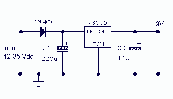
There is little to be said about this circuit. All the work is done by the regulator. The 78S09 can deliver up to 2 amps continuous output whilst maintaining a low noise and very well regulated supply. The circuit...
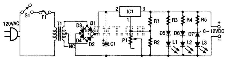
This 0- to 12-Vdc variable power supply utilizes an integrated circuit (IC) voltage regulator along with a robust transformer to deliver a dependable DC power output. The schematic illustrates that transformer T1 has a primary voltage of 120 V...
The WSH412 is designed to integrate a Hall sensor with complementary output drivers and a frequency generator on a single chip. It is suitable for applications such as speed measurement, revolution counting, positioning, and DC brushless motors. The device...
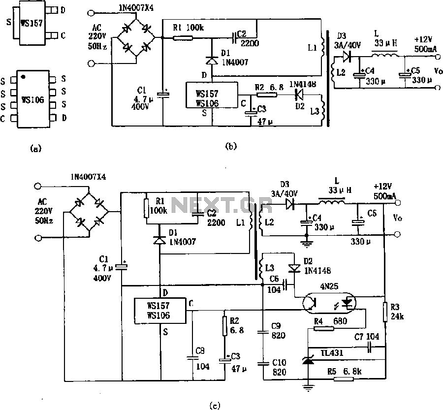
The WS157 or WS106 is a low-power miniature switching power supply that has been developed in recent years. It functions as a regulated switching power supply control device, featuring integrated internal control circuitry and power switches on a single...
The circuit involves powering an LED using a 3V CR2032 battery, with the intention of extending battery life by making the LED blink rather than remain continuously on. A 555 timer is considered, utilizing large value resistors in the...
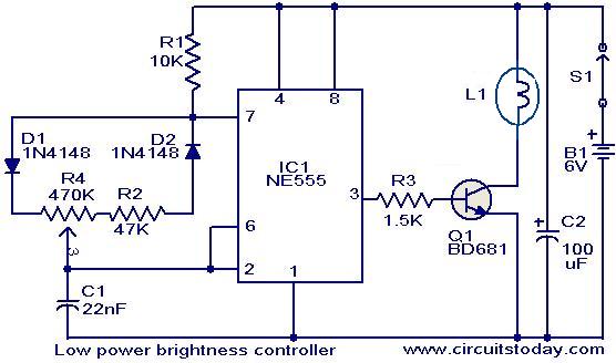
The circuit presented here is designed to control the brightness of low-power incandescent lamps. It utilizes the NE555 integrated circuit, configured as an astable multivibrator with a variable duty cycle. The output from the IC is connected to the...
Warning: include(partials/cookie-banner.php): Failed to open stream: Permission denied in /var/www/html/nextgr/view-circuit.php on line 713
Warning: include(): Failed opening 'partials/cookie-banner.php' for inclusion (include_path='.:/usr/share/php') in /var/www/html/nextgr/view-circuit.php on line 713