
AC triggered switch

The described circuit functions as an AC-triggered switch designed for low-frequency signal applications. It employs two transistors, Q1 and Q2, configured as common emitter amplifiers, which are pivotal in controlling the flow of current to the load, represented by a relay.
Transistor Q1 is biased through resistors R3 and R4, establishing a base voltage of approximately 0.5V. This biasing is crucial as it ensures that in the absence of an input signal, both transistors remain in the off state, thus preventing any current flow through the load. The circuit is designed to respond to input signals above a threshold of 0.3V peak-to-peak (equivalent to 100mV RMS).
When an input signal exceeds this threshold, the positive half-cycle of the AC waveform activates Q1, allowing current to flow through Q2, which subsequently energizes the relay. This action effectively closes the circuit, enabling power to the load. As the input signal transitions into its negative half-cycle, Q1 turns off, but Q2 continues to conduct due to the base current flowing through capacitor C. This behavior ensures that the relay remains activated for the duration of the positive half-cycle, providing a stable output despite the AC signal's fluctuations.
The overall design is characterized by its simplicity and reliance on discrete components, making it a cost-effective solution for applications requiring reliable switching mechanisms in response to low-frequency AC signals. The careful selection of component values, particularly the biasing resistors and the capacitor, is essential for optimizing the circuit's performance and responsiveness to input signals.An AC triggered switch for low frequency signals. This is a basic ac voltage operated switch made from discrete components. Both Q1 and Q2 work as common emitter amplifiers, but the biasing of Q1 is arranged by R3 and R4 so that about 0.5V is applied to its base; so with no input signal both transistors and the load is off. With an input signal greater than 0.3V pk-pk (100mV RMS) the positive half of the waveform will switch on Q1, and Q2 and the relay. As the input signal switches to its negative transition, Q1 will switch off, but base current in Q2 continues to flow via C
🔗 External reference
Related Circuits
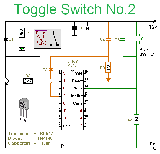
This circuit utilizes a CMOS 4017 decade counter, which begins counting from zero and advances by one each time pin 14 is activated. Upon reaching nine, the count resets to zero and starts over. As the count progresses, each...
The circuit is designed to provide protection to a DIY switching power supply for car amplifiers by shutting down under any or all of the three modes of protection (over voltage, under voltage and over temperature) with minimal components. The...
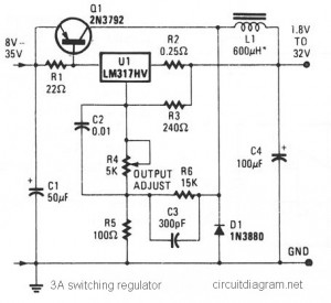
The circuit diagram presented is a simple and cost-effective switching voltage regulator capable of delivering an adjustable output voltage range from 1.8V to 32V with a maximum static current of 3A. This regulator utilizes the adjustable LM317HV IC along...
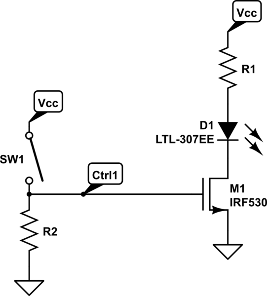
A 4-position slide switch is utilized to activate different colored LEDs based on its position. Additionally, it is required to adjust the output frequency of a 555 timer operating in astable mode to drive a piezo buzzer. The challenge...
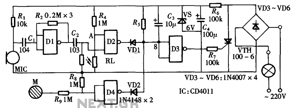
The circuit integrates sound and light control with touch functionality, creating a fully operational delay section light switch circuit. It consists of light control, voice circuits, and a touch control circuit, all triggered by a thyristor switch. The described circuit...
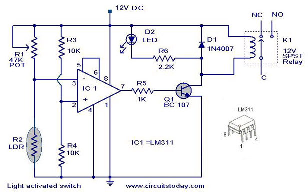
The following circuit illustrates a Light Activated Switch Circuit Diagram. This circuit is based on the LM311 integrated circuit, which functions as a voltage comparator. The Light Activated Switch Circuit utilizes the LM311 voltage comparator to control the switching of...