
3A Switching Voltage Regulator based LM317HV

The circuit operates effectively as a versatile power supply solution, suitable for various applications requiring adjustable voltage and stable output. The use of the LM317HV allows for a wide range of output voltages, which can be tailored to specific requirements by adjusting external resistors. The inclusion of the PNP transistor enhances current handling capabilities, making the circuit suitable for driving loads that demand more than the standard output of the LM317HV alone.
The IC8211 is integral to maintaining voltage stability and precision, providing a reference that ensures the output remains consistent even under varying load conditions. The selection of capacitors C1 and C2 is critical for ensuring stability in the feedback loop, while C3 serves to filter out any low-frequency noise that may affect the performance of the voltage regulator.
In applications where solar power is utilized, the design effectively manages the charging of a battery, ensuring that the system can operate independently of the grid. The use of a diode prevents reverse current flow, protecting the solar panel and ensuring efficient energy transfer to the battery. The automatic light controller functionality demonstrates the circuit's adaptability, allowing it to respond to environmental conditions by adjusting the output based on light availability.
Overall, this circuit design exemplifies a practical approach to voltage regulation and power supply management, combining adjustable outputs with robust performance in a range of operational scenarios. Proper selection and configuration of components are essential to achieve the desired performance characteristics, ensuring reliability and efficiency in the final application.Above circuit diagram is a easy, simple and cheap switching voltage regulator which has capability to deliver adjustable voltage output range of 1. 8V to 32V and static electric current of 3A. This regulator use adjustable regulator IC of LM317HV and a power PNP transistor of 2N3792. Positive voltage regulator circuit with PNP Boost transistor The IC8211 presents the voltage reference and regulator amplifier, while Q1 will be the series pass transistor. R1 defines the output current of the IC8211, while C1 and C2 present loop stability and as well act to suppress feedthrough of input transients to the output supply.
R2. This is the circuit diagram of automatic light controller which use 78xx voltage regulator IC series. The voltage regulator ICs deliver a constant output voltage, as against a extensively fluctuating input supply, when the common terminal is grounded.
Any voltage about zero volt (ground) interconnected within the common terminal is added to the output voltage. . By default, the regulator ID 78xx series will give maximum current output 1A - 1. 5A. To increase the current output of this regulator, you may consider this circuit. Parts list: R1, R2 = 4. 7 K C1, C2 = 4700 uF / 16V C3 = 47, 000 uF / 35V D1, D2, D3 = 1N5401 ( 3 Amp. Powered with solar panel, the circuit will give you 5V pure regulated DC voltage. The circuit is made up of an oscillator transistor as well as a regulator transistor. The solar panel charges the battery when sunlight is bright enough to generate a voltage above 1. 9v. A diode is necessary between the panel and also. This is power supply circuit which have 2 output that are static output and adjustabled output. The static output is stabled and regulated output. The circuit is based around the 7805 voltage regulator. It has only 3 connections (input, output and ground) and it provides a fixed output. The last two digits of the part. 🔗 External reference
Related Circuits
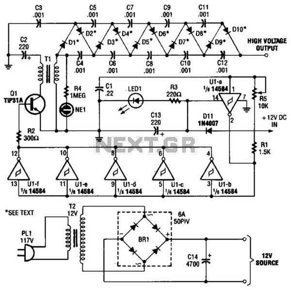
In the miniature high-voltage DC generator, the circuit receives input from a 12 V DC power supply, which is amplified to produce a 10,000 V DC output. This process induces a pulsating signal of opposite polarity in the secondary...
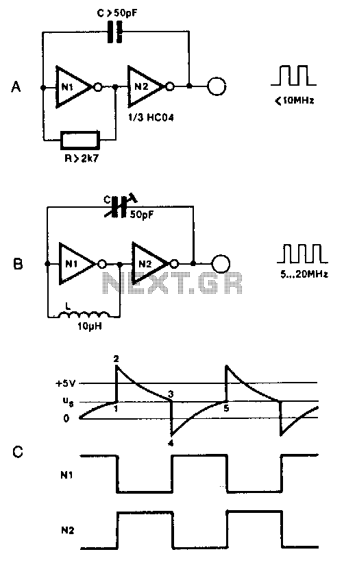
Two inverters, one resistor, and one capacitor are sufficient to create an HC(T)-based oscillator that operates reliably up to approximately 10 MHz. The use of two HC inverters results in a fairly symmetrical rectangular output signal. In this configuration,...
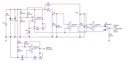
The goal is to control the speed of a 6-volt brush DC motor using a linear potentiometer and to create an oscillating speed effect, with the oscillation frequency also adjustable via a linear potentiometer. The desired complete cycle peak-to-peak...
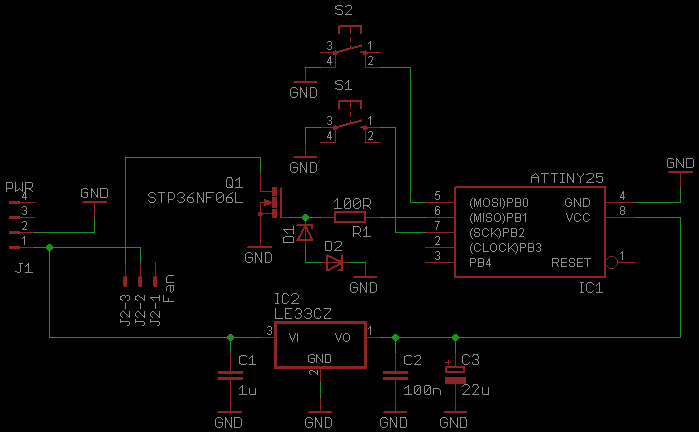
This document serves as a continuation of the previous work on PWM controllers utilizing 555 timers. The new design incorporates microcontrollers and MOSFETs in place of the 555 integrated circuits and transistors. Two versions have been developed: one equipped...
The output of the transformer has been calculated to be 125 times higher than the input, based on the ratio of 1000 to 8. Given an input of 12V, the expected output should be 1500V, although there is some...
This circuit is not a novelty, but it proved so useful, simple and cheap that it is worth building. When the positive (Red) probe is connected to a DC positive voltage and the Black probe to the negative, the...