
Sound and light control touch delay saving switch integrated circuit diagram
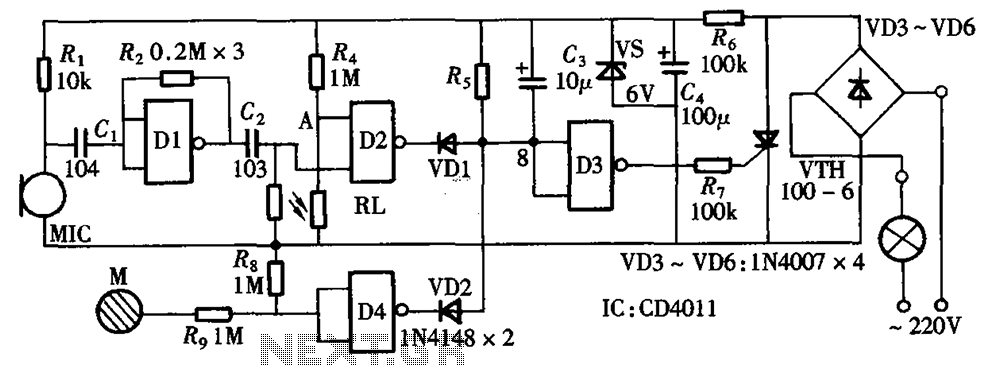
The described circuit serves as a multifunctional delay light switch, effectively combining three distinct control mechanisms: light sensing, sound activation, and touch input. The core component of this system is a thyristor switch, which acts as the primary trigger for the circuit's operation.
The light control circuit is designed to detect ambient light levels. When the light falls below a predetermined threshold, the circuit activates the thyristor, allowing current to flow and illuminating the connected light source. This function is particularly useful for automatic lighting in dark environments.
The voice control circuit utilizes a microphone and signal processing components to detect specific sound patterns or commands, which also trigger the thyristor. This feature allows users to control the lighting through vocal commands, enhancing convenience and accessibility.
The touch control circuit incorporates a touch-sensitive interface that enables users to manually activate or deactivate the light by simply touching the designated area. This feature provides a direct and intuitive method of control, complementing the automated functions of the light and voice circuits.
Overall, the integration of these three functionalities into a single circuit not only enhances the user experience but also promotes energy efficiency by ensuring that the light is only activated when necessary. The use of a thyristor switch ensures reliable operation and quick response times, making the circuit suitable for various applications, including home automation systems and smart lighting solutions. As shown in the circuit with a set of sound and light control touch three functions into one to form a fully functional delay section light switch circuit as shown in FIG. Part of the circuit, light control circuit, voice circuits and touch control circuit is triggered by a thyristor switch.
Related Circuits

This design circuit functions as an alarm system controlled by a keypad. The core component of the circuit is a single transistor from the BC547 series. The circuit requires a 12-key pad, which has 13 terminals; a matrix type...
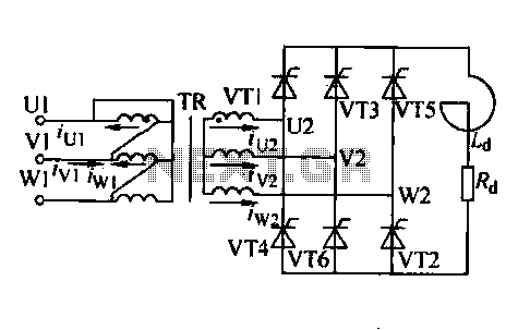
Trigger circuit routing forms include various types such as simple trigger circuits, single-junction transistor trigger circuits, synchronous sine wave trigger circuits, sawtooth transition phase shift (synchronous) trigger circuits, and integrated trigger circuits. This section presents individual cases for introduction...
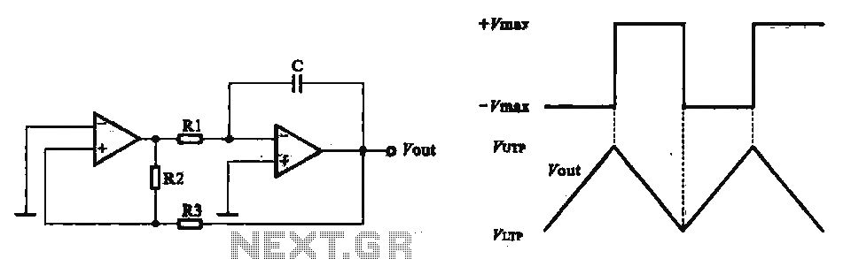
This circuit utilizes two operational amplifiers configured as triangular wave oscillators. It demonstrates a practical application of a relaxation oscillator that employs a voltage comparator to execute the switching function. The schematic in FIG. 2 illustrates the composition of...
A guide for creating a remote power switch for a DC to AC inverter. The purpose is to enable the user to turn the inverter on and off remotely. The design of a remote power switch for a DC to...
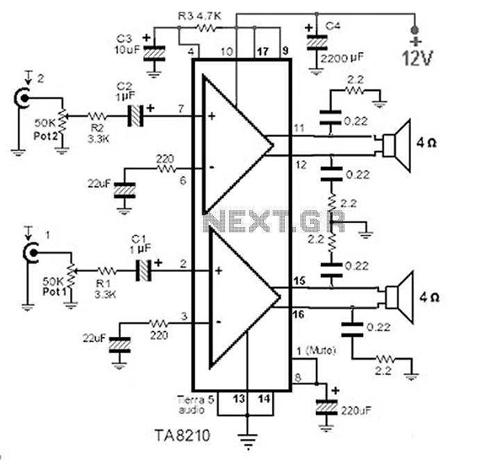
This circuit consists of a 2 x 22 watt BTL amplifier utilizing the IC TA8210AH. It functions not only as an automobile amplifier but is also suitable for low-frequency sound applications, particularly in high-fidelity audio systems, due to its...
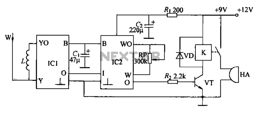
A circuit for an inductive burglar alarm is derived from a radio scanning detection circuit, which includes a signal processing circuit and an alarm circuit. The radar detection circuit module consists of components such as microwave emission, low-pass filtering,...
Warning: include(partials/cookie-banner.php): Failed to open stream: Permission denied in /var/www/html/nextgr/view-circuit.php on line 713
Warning: include(): Failed opening 'partials/cookie-banner.php' for inclusion (include_path='.:/usr/share/php') in /var/www/html/nextgr/view-circuit.php on line 713