
555 IC using a delay circuit of the four b

The circuit utilizes the 555 IC in monostable mode, where it generates a single output pulse in response to a triggering event. When the button SB is pressed, it triggers the 555 IC, causing the output to go high. The duration for which the output remains high is determined by the resistor (R) and capacitor (C) values connected to the 555 timer. The delay time (t) can be calculated using the formula t = 1.1 * R * C, where R is the resistance in ohms and C is the capacitance in farads. The inclusion of the adjustable potentiometer (RP) allows for fine-tuning of the resistance, thereby varying the delay time according to the application needs.
Once the delay time elapses, the output of the 555 IC transitions to a low state, effectively turning off the connected load. The load is powered through a unidirectional thyristor circuit, which is designed to conduct current only during one half of the AC cycle. This configuration ensures that the load receives power in a controlled manner, providing efficient operation and reducing the risk of overheating or damage to the components involved.
Overall, this circuit is suitable for applications requiring timed control of a load, such as in lighting systems, motor controls, or other automated processes where a delay is necessary before deactivating the load. The combination of the 555 timer, adjustable delay, and thyristor control creates a versatile and effective solution for various electronic applications.555 IC using a delay circuit of the four b They are a jump from high to low transition of the delay circuit. That button is pressed SB snow, the output is high, after some dela y, the output of the transition to the low level and remain low. Adjustment potentiometer RP, can change the delay time. Unidirectional thyristor circuit, called on to supply the load only half-wave power.
Related Circuits
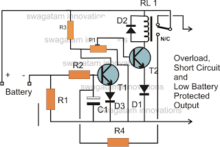
The battery voltage must pass through resistor R1 before reaching the output load. As a result, the current flowing through R1 is proportionately transformed into a voltage across it. When the battery voltage drops below a certain threshold, the...
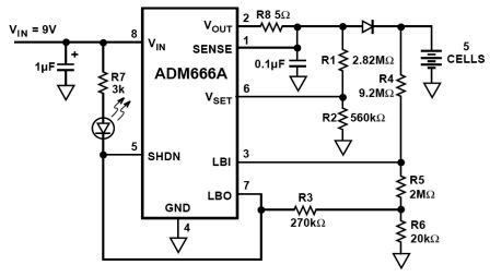
NiMH charger circuit diagram using ADM66A. Related searches include charger circuit, NiMH charger circuit, lead acid battery charger circuit, LiPo charger circuit, automatic battery charger circuit, simple battery charger circuit, lithium battery charger circuit, charger circuit diagram, and 12V...

This automatic light dimmer circuit enables controlled lighting that gradually turns on or off. The operation is as follows: when switch S1 is closed, capacitor C1 charges slowly. Once the voltage across C1 reaches 0.6 volts, transistor T1 begins...
The impedance of these current generators is essentially infinite for small currents, and they maintain accuracy as long as VIN is significantly greater than VOS and IO is much higher than I bias. The source employs a FET to...
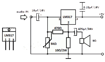
The LM317 integrated circuit (IC) is commonly recognized as a voltage regulator; however, it can also function as an audio amplifier. This low-power amplifier circuit designed with the LM317 provides a maximum output of approximately 1 watt. The LM317...
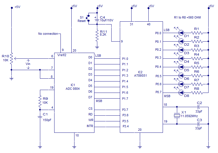
Interfacing ADC to 8051 microcontroller. ADC0804 is interfaced to microcontroller AT89S51. Complete circuit, theory and program in assembly language. The interfacing of an Analog-to-Digital Converter (ADC) with a microcontroller is a critical aspect of embedded systems design, particularly when analog...