
Solid-state relays control the motor forward and reverse operation circuit

The circuit operates by utilizing a single-pole double-throw (SPDT) switch, referred to as the SA switch, which allows the user to toggle between the forward and reverse states of the motor. In the work position, the switch completes the circuit to the motor, enabling it to run in the forward direction. Conversely, when the switch is flipped to the reverse position, the polarity of the voltage applied to the motor terminals is reversed, causing the motor to rotate in the opposite direction.
To protect the circuit from over-voltage conditions, an over-voltage protection element is incorporated. This element is critical in safeguarding the motor and associated circuitry from voltage spikes that could potentially cause damage. The design of the over-voltage protection may include components such as zener diodes or transient voltage suppressors (TVS), which can clamp excessive voltage and direct it safely to ground.
In addition to the over-voltage protection, the circuit includes resistive-capacitive (RC) networks and resistors (R) as indicated in Figure 3-13. These components may be used for various purposes, including filtering, timing, or signal conditioning, depending on the specific application requirements. The RC network can help in smoothing out voltage variations and providing stability to the circuit operation.
Overall, this circuit design is suitable for applications requiring controlled motor direction with built-in protection mechanisms, ensuring reliable operation under various electrical conditions. Circuit shown in Figure 3-14. SA switch placed in the work position, the motor is transferred; SA placed bit is set, reverse the motor. Drawing, over-voltage protection element RC and R, with the choice of Figure 3-13.
Related Circuits
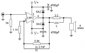
Almost all audio power amplifiers utilize integrated circuit amplifiers, such as the M12CLK, which is a power operational amplifier. This amplifier allows for an output stage that operates at an impedance of 2 ohms and provides a power gain...
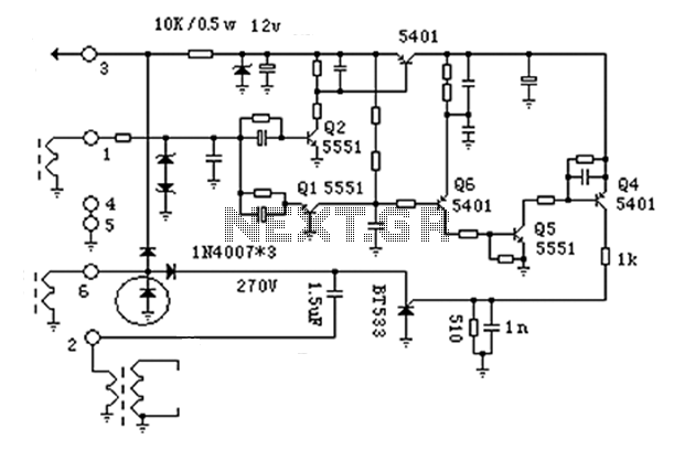
Working with lasers can be enjoyable and intriguing, but it can also be costly. High voltage power supplies for laser tubes are often more expensive than the tubes themselves. However, this power supply can be constructed using common components...
The anatomy of two ignition experiments revealed a common issue, specifically that both ends of the ignition coil are equipped with a diode. This design choice by manufacturers has implications for performance. The ignition coil generates a negative half-cycle...
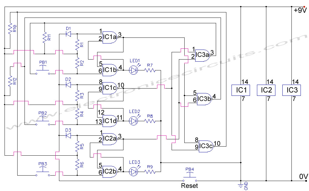
First Response Monitor, Input Selector, Game Circuit. This circuit is utilized for first response applications as it aids in monitoring various responses in games. The First Response Monitor circuit is designed to facilitate real-time monitoring and selection of input signals...
The circuit is an amplifier with bias at cutoff. Transistor Q5 functions similarly to a grid-leak detector. In the absence of a subcarrier input, the demodulator is disabled, preventing any signals from passing through. It is essential for the...

The Univibe is a footpedal-operated phaser or phase shifter designed to generate chorus and vibrato simulations for electric organs or guitars. It was introduced in the 1960s by Shin-ei, with the intention of emulating the "Doppler sound" characteristic of...